
Method for performing an emergency stop using a declaration profile of an electric motor

a technology of electric motor and emergency stop, which is applied in the direction of elevators, transportation and packaging, etc., can solve the problems of unnecessarily large deceleration difference, unnecessary large deceleration difference, etc., and achieve the reduction of the braking torque of the machinery brake, the effect of improving the reliability of the brakes and simplifying the structur

Active Publication Date: 2019-02-05
KONE CORP
View PDF19 Cites 12 Cited by
  • Summary
  • Abstract
  • Description
  • Claims
  • Application Information

AI Technical Summary

Benefits of technology

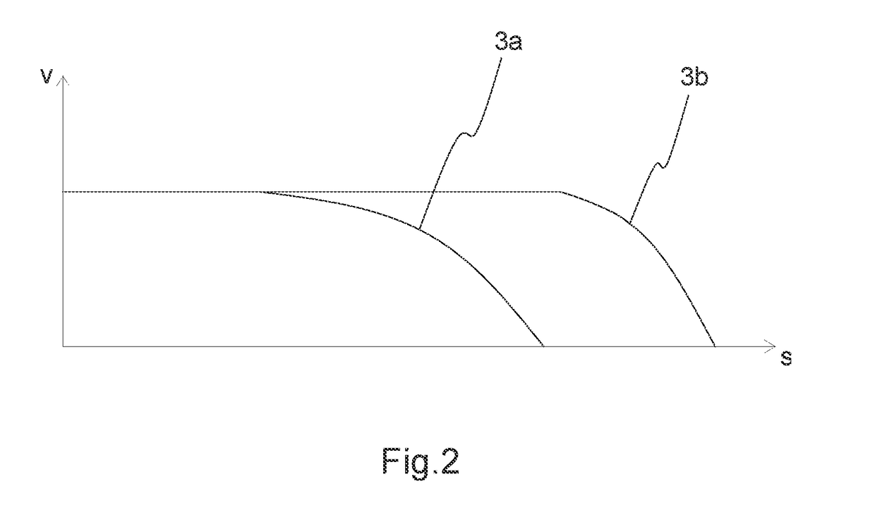
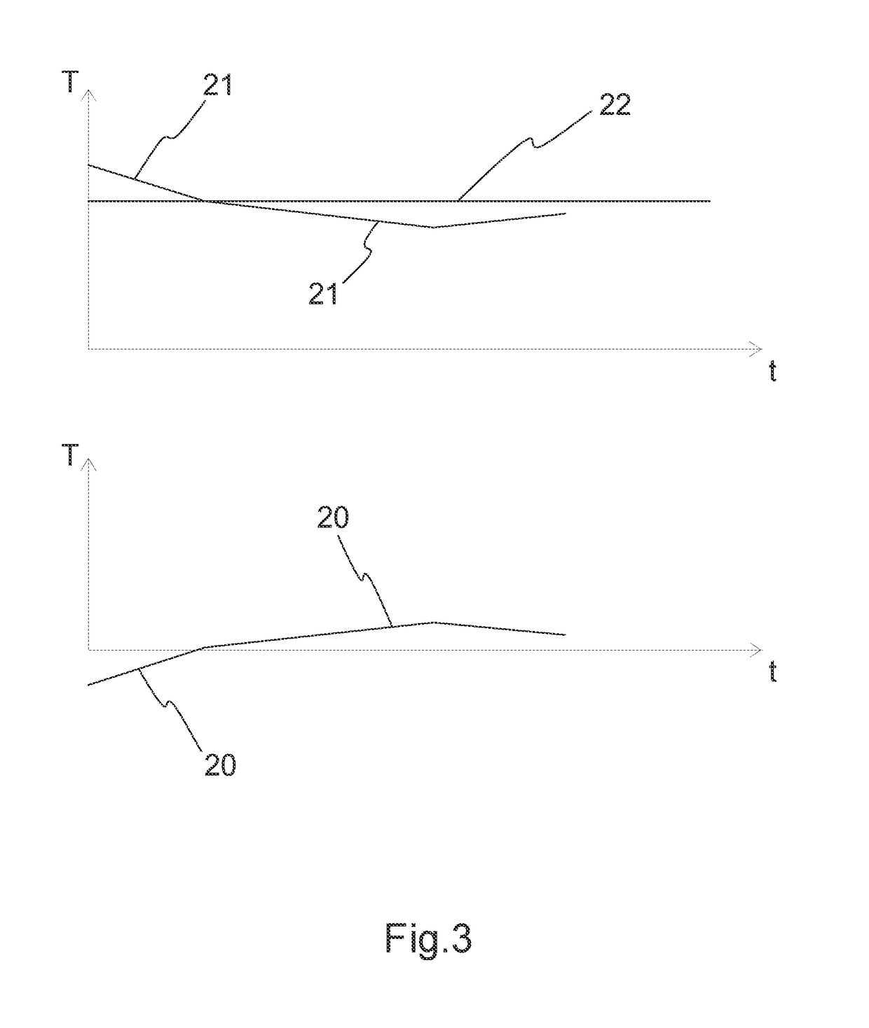
[0013]In some embodiments the machinery brake is connected to brake the traction sheave of the hoisting machine of the elevator at the same time as the elevator car is driven with the electric motor of the hoisting machine to a stop. This means that only one of the machinery brakes is connected to brake the traction sheave of the hoisting machine. In this case the braking can be performed using simultaneously for braking both a machinery brake and also the motor braking of the electric motor of the hoisting machine. Also the adjustment need / tolerance requirements of the braking torque of the machinery brake decrease because variation of the braking force of the machinery brake can be compensated with the electric motor of the hoisting machine. The braking force can vary e.g. owing to ambient conditions; in addition, there can be a unit-specific difference between different brakes. Consequently, if a machinery brake does not brake sufficiently, then braking is performed also with the electric motor of the hoisting machine. If the braking force of the machinery brake, and consequently the deceleration of the traction sheave, is excessive, on the other hand, the electric motor drives against the brake in such a way that the deceleration remains according to the given deceleration profile. By means of the solution a unit-specific variation in braking force between different brakes that is larger than before can be permitted, in which case the structure of the brakes can be simplified. At the same time the reliability of the brakes improves and also costs decrease.

Problems solved by technology

Engagement of the brakes might cause unnecessarily large deceleration, which feels unpleasant to the passengers and in the worst case might cause slight injury.
Particularly in elevators without a counterweight as well as in elevators having, e.g. for energy-saving reasons, a counterweight that is lighter than normal, the difference between the smallest and greatest deceleration during an emergency stop can be unnecessarily large when braking with the machinery brakes.

Method used


Image

  • Method for performing an emergency stop using a declaration profile of an electric motor
  • Method for performing an emergency stop using a declaration profile of an electric motor
  • Method for performing an emergency stop using a declaration profile of an electric motor

Examples


Embodiment Construction

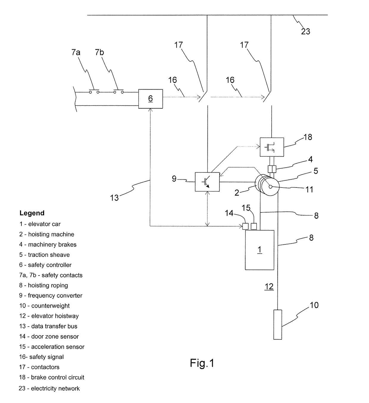
[0024]For the sake of clarity, FIGS. 1-3 endeavor to present only the features that are essential from the viewpoint of understanding the invention. Consequently e.g. some generally known parts belonging to an elevator are not necessarily presented in the figures if the presentation of them is not significant from the viewpoint of understanding the invention.

[0025]FIG. 1 presents a safety arrangement in an elevator, in which the elevator car 1 is moved in the elevator hoistway 12 by pulling the hoisting roping 8 of the elevator car with the traction sheave 5 of the hoisting machine 2. The elevator car 1 is driven by rotating the traction sheave 5 with an electric motor in the hoisting machine 2, by supplying current to the electric motor from the electricity network 23 with a frequency converter 9. The elevator car 1 is also braked by the electric motor of the hoisting machine 2 with motor braking, in which case electric power returns to the frequency converter 9, from where it is s...


PUM


Abstract

A method for performing an emergency stop with an elevator and a safety arrangement of an elevator. In the method, when an emergency stop criterion is fulfilled, the elevator car is driven with the electric motor of the hoisting machine to a stop with a given deceleration profile.

Description

CROSS REFERENCE TO RELATED APPLICATIONS[0001]This application is a Continuation of PCT International Application No. PCT / FI2014 / 050683, filed on Sep. 8, 2014, which claims priority under 35 U.S.C. 119(a) to Patent Application No. 20135913, filed in Finland on Sep. 10, 2013, all of which are hereby expressly incorporated by reference into the present application.FIELD OF THE INVENTION[0002]The invention relates to solutions for performing an emergency stop with an elevator.BACKGROUND OF THE INVENTION[0003]In an emergency stop situation of an elevator the elevator car is stopped by disconnecting the supply of electric power to the electric motor of the hoisting machine of the elevator, as well as simultaneously connecting machinery brakes, of which there are usually two, to brake the traction sheave of the hoisting machine.[0004]Different elevators can be counterweighted for different loads. The load of the elevator also varies from one run to another. Consequently, during an emergenc...

Claims


Application Information

Patent Timeline
Patent Type & Authority Patents(United States)
IPC IPC(8): B66B1/32B66B5/04B66B5/00B66B1/30B66B1/24B66B5/02
CPCB66B5/02B66B1/24B66B5/04B66B1/32B66B5/0031B66B1/30
Inventor KATTAINEN, ARIHOVI, ANTTIKANGAS, PETTERISTOLT, LAURI
Owner KONE CORP
Learn More