Hydrocarbon leak imaging and quantification sensor

a technology of hydrocarbon leak imaging and quantification sensor, which is applied in the direction of optical radiation measurement, instruments, spectrometry/spectrophotometry/monochromator, etc., can solve the problems of health hazards, requiring direct sampling in place, and creating both safety and environmental hazards

Active Publication Date: 2019-02-05
MULTISENSOR SCI INC
View PDF30 Cites 12 Cited by
  • Summary
  • Abstract
  • Description
  • Claims
  • Application Information

AI Technical Summary

Benefits of technology

[0019]This invention has several key advantages over thermal infrared gas imaging sensors that operate in the mid-wave (MWIR) or long-wave (LWIR) infrared parts of the spectrum. This includes the ability to detect and quantify leaked gas with small or no temperature difference relative to the background, as the invention utilizes SWIR light provided by natural sunlight or by lamps of appropriate color temperature, and does not rely on a thermal contrast between gas and the background or a background of varying temperature. The detectors suitable for use in this invention do not require cryogenic cooling, using instead thermo-electric cooling that is more reliable and less expensive than cryogenic coolers such as a Stirling engine or liquid nitrogen. Finally, the invention can also detect gas leaks in the presence of humidity, steam, fog, and light rain, as the hydrocarbon features detected in the SWIR do not overlap spectral regions where water vapor absorption is significant, which is important as one cannot control the presence of water vapor or fog in the atmosphere between the sensor and the leak source, and many industrial processes purposely mix steam with hydrocarbon gases.
[0020]This invention and its various embodiments will be useful in imaging, detecting, localizing, and quantifying natural gas leaks from components along the entire gas supply chain, from the well head to compressors to transmission pipelines to gate stations and underground distribution networks. Detection and quantification of volatile organic compounds (VOCs) in or near refineries, petrochemical plants, hydrocarbon storage tanks, or other industrial and commercial facilities will be possible. Landfill methane emissions mapping will be possible using this invention in combination with tomographic imaging around the periphery of a landfill. Similar tomographic three-dimensional mapping of gas over a refinery is possible, utilizing an airborne variant of this invention. This invention has also been shown to be capable of detecting liquid oil spills on land, sand, seawater, and sea ice. Other embodiments of the invention will prove useful in detecting and mapping oil films and emulsions at sea, oil spills in arctic waters, tar balls on beach sand, and damage to wetlands from oil spills. The embodiments of the invention described herein are suitable for packaging in the form of, for example, hand-portable imaging sensors, ground vehicle-mounted inspection systems, vessel-mounted sensing systems, airborne surveying systems, relocatable trailer-mounted and fixed-site monitoring systems.

Problems solved by technology

Natural gas leaks create both safety and environmental hazards, and occur along the entire gas supply chain from the well to the street (so-called upstream, midstream, and downstream sectors).
Other hydrocarbons found in natural gas, as well vapors emanating from liquids separated from gas and oil include ethane, propane, butane, pentane, hexane, octane, and heavier hydrocarbons, which form volatile organic compounds that generate smog which is a health hazard.
They can be fixed in place for continuous monitoring, or hand portable for inspections, but they require direct sampling in place and provide very limited coverage.
They may provide concentration measurements, but do not provide leak rate estimates.
These sensors detect gas present anywhere along the line between the light emitter and the photo-detector (or between combined emitter / detector assembly and a remote reflector if the optical path is folded), but they cannot determine where along the path the gas is, nor from where it came, and has limited coverage to only the narrow open path between emitter and detector.
By utilizing multiple wavelengths of light, such sensors can measure column density of gas along the open path, but cannot measure or estimate concentration nor leak rate.
The leading commercially available gas imaging sensors operate in only a single narrow band of the mid-wave infrared spectrum, and do not provide quantitative data, only pictures to be interpreted by the human operator.
Such systems have proven to be both expensive and have significant shortcomings.
This requires that the background and gas differ in temperature by at least several degrees Celsius, otherwise the light absorbed (or emitted) by the gas will not provide sufficient signal contrast to be reliably detected by the human operators of these thermal sensors.
Thus, there is little or no thermal contrast between the gas and the ground, and so cannot be reliably detected by a thermal infrared sensor.
Another major shortcoming of mid-wave and long-wave gas imaging sensors is their poor performance in the presence of water vapor (high humidity, steam), fog and light rain.
Thus, water vapor will mask the presence of a methane leak, and conversely, water vapor will trigger a false alarm for methane.
Additionally, all mid-wave infrared and some long-wave infrared gas imaging sensors require cryogenic cooling, which is both expensive and unreliable.
Finally, none of the available gas imaging sensors provides a capability to estimate leak rate from a hole, or emission flux from a surface.

Method used


Image

  • Hydrocarbon leak imaging and quantification sensor
  • Hydrocarbon leak imaging and quantification sensor
  • Hydrocarbon leak imaging and quantification sensor

Examples


Embodiment Construction

Principals of Gas Absorption Imaging

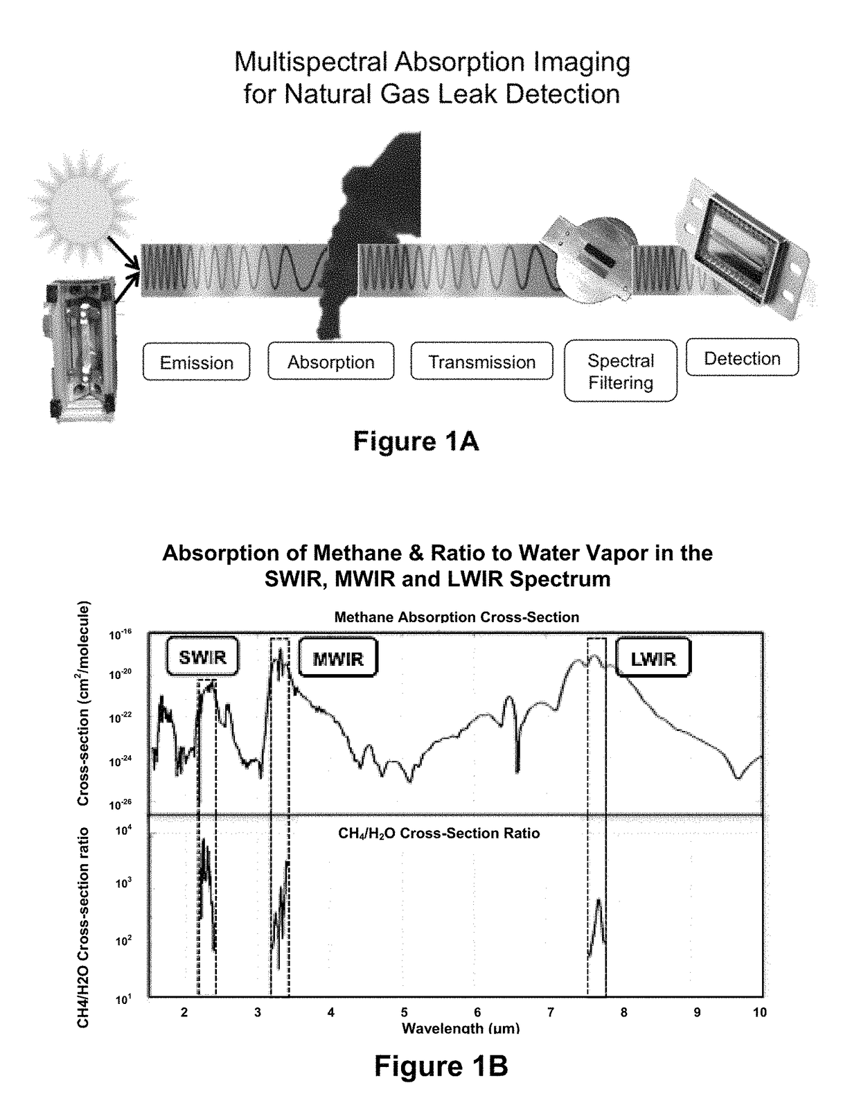
[0050]This invention detects gas leaks via differential absorption imaging spectroscopy in the range 1.0 to 2.6 microns, exploiting spectral features of hydrocarbons in the short-wave infrared (SWIR) region, primarily in the wavelength range of 2.0 to 2.5 microns. These wavelengths are not typically associated with those in the thermal emission regions of the mid-wave infrared (MWIR) and long-wave infrared (LWIR) for objects at terrestrial temperatures. Appreciable thermal emission at around 2.0 microns requires objects at temperatures of around 1000° C. Instead, this invention relies on illumination sources like natural sunlight and lamps of color temperature near 1000° C. Thus, the invention can detect hydrocarbons at the same temperatures as their backgrounds by using external illumination instead of thermally emitted light.

[0051]The principals underlying non-thermal infrared multispectral imaging of a gas leak are shown in FIG. 1A. SWIR radiat...


PUM

PropertyMeasurementUnit
wavelength rangeaaaaaaaaaa
lengthaaaaaaaaaa
widthaaaaaaaaaa

Abstract

This invention consists of sensors and algorithms to image, detect, and quantify the presence of hydrocarbon gas (for example from leaks) using a short-wave infrared radiation detector array with multiple spectral filters under natural sunlight or artificial illumination, in combination with the hydrodynamics of turbulent gas jets and buoyant plumes. Multiple embodiments are recited and address detection and quantification of methane gas leaks. Quantification includes gas column densities, gas concentration estimates, total mass, hole size estimates, and estimated emission flux (leak rate) of gas from holes and cracks in pressurized vessels, pipes, components, and general gas infrastructure, and from surface patches (for example due to gas leaks in underground pipes) under the action of buoyancy and wind. These and similar embodiments are applicable more generally to natural gas and other hydrocarbon gases, liquids, emulsions, solids, and particulates, and to emissions monitoring of greenhouse gases methane and carbon dioxide.

Description

CROSS-REFERENCE TO RELATED APPLICATIONS[0001]This application claims priority from provisional patent applications U.S. 62 / 338,255 filed 2016 May 18, and U.S. 62 / 472,463 filed 2017 Mar. 16, both by the present inventors.FEDERALLY SPONSORED RESEARCH[0002]NoneSEQUENCE LISTING[0003]NoneTECHNICAL FIELD OF INVENTION[0004]This invention refers generally to optical detection and quantification of natural gas and other hydrocarbon gas leaks, from holes and cracks in pressurized vessels, pipes, components, and general gas infrastructure, and from emissions emanating from surfaces due to gas leaks in underground gas infrastructure or naturally occurring surface emissions. It may also be useful in assessing methane emissions from livestock.BACKGROUND—PRIOR ART[0005]Landau, L. D., & Lifshitz, E. M., “Fluid Mechanics”, Pergamon Press (1959).[0006]Abramovich, G. N., “The Theory of Turbulent Jets”, MIT Press (1966).[0007]Thomas, G. E., & Stamnes, K., “Radiative Transfer in the Atmosphere and Ocean...

Claims


Application Information

Patent Timeline
Patent Type & Authority Patents(United States)
IPC IPC(8): G01M3/38G01N21/85G01N21/31G01N33/00G01N21/359G01N21/3504G01F1/66G01J3/28
CPCG01M3/38G01N21/31G01N21/3504G01N21/359G01N33/0036G01N21/85G01N2021/3531G01F1/661G01J2003/2826G01N2021/3513G01N2021/8578Y02A50/20
Inventor WAXMAN, ALLEN M.BYLSMA, JASON M.VAITSES, ALLAN
Owner MULTISENSOR SCI INC
Why Eureka
Try Eureka