
Systems and methods for isolating condensate in a condensation particle counter

a technology of condensation particle counters and counters, applied in the direction of instruments, suspensions and porous materials analysis, material analysis, etc., can solve the problems of affecting the quality of condensate, and causing further problems

Active Publication Date: 2019-02-05
PARTICLE MEASURING SYST
View PDF32 Cites 16 Cited by
  • Summary
  • Abstract
  • Description
  • Claims
  • Application Information

AI Technical Summary

Benefits of technology

The systems and methods described in this patent are designed to prevent the migration of condensate in a condensation particle counter. This is accomplished by automatically engaging to protect sensitive components when the counter is not in use or powered. The systems can be used with different counting systems and even allow for the shipping or transport of a condensation particle counter with the condensate in situ. The technical effects of this invention include increased protection and preservation of the components, improved shipping and transport capabilities, and improved efficiency and accuracy of mitigating the effects of condensate on sensitive components.

Problems solved by technology

Depending on the particle detection device, the condensate may be harmful if allowed to interact with the sensitive components of the detection system or problematic if allowed to interfere with the small volumes of the flow control devices.
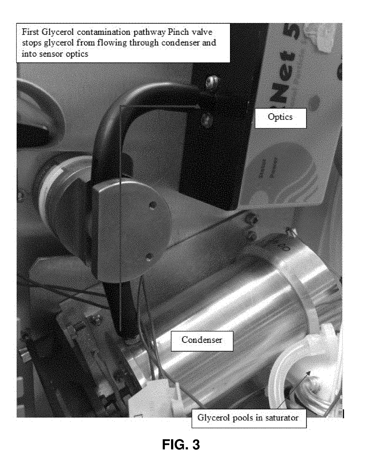
Thus, problems can arise when the condensation particle counter system is moved, either within a laboratory or transported to a different destination, as the condensate may migrate away from the saturator and condenser components and into the optics or flow control devices.
This problem is compounded if the system is not maintained in an upright position during transportation, as the saturator and condenser are often positioned to prevent condensate migration while the system is upright.
These problems are further magnified when a viscous and / or wettable condensate (e.g. glycerol) is used in the condensation particle counter system.
This leads to condensate migration problems during shipping, even if the condensate reservoir has been drained and device is shipped or transported after the vast majority of the condensate has been removed.

Method used


Image

  • Systems and methods for isolating condensate in a condensation particle counter
  • Systems and methods for isolating condensate in a condensation particle counter
  • Systems and methods for isolating condensate in a condensation particle counter

Examples


example 1

Isolation of Condensate Tied to System Power

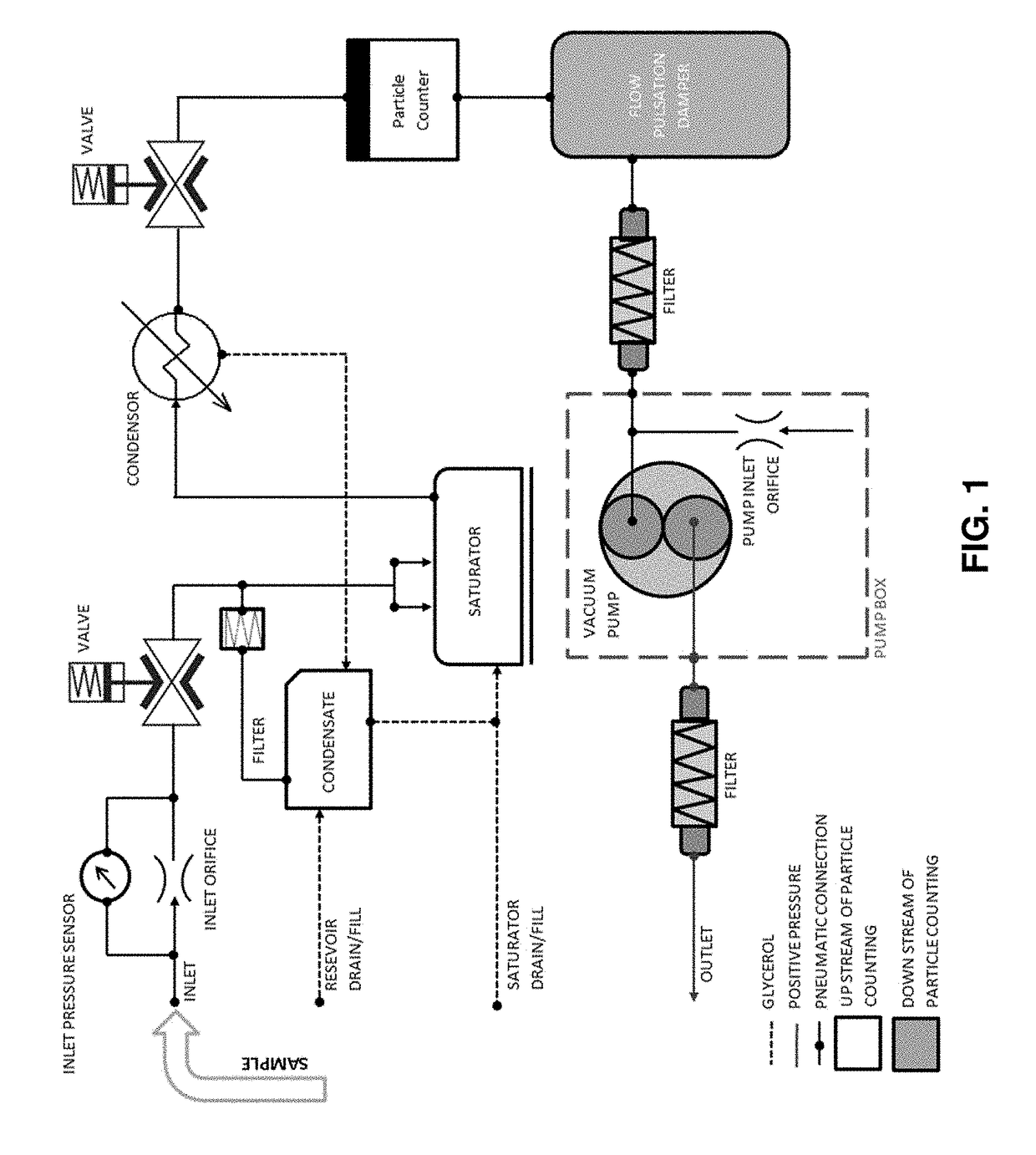
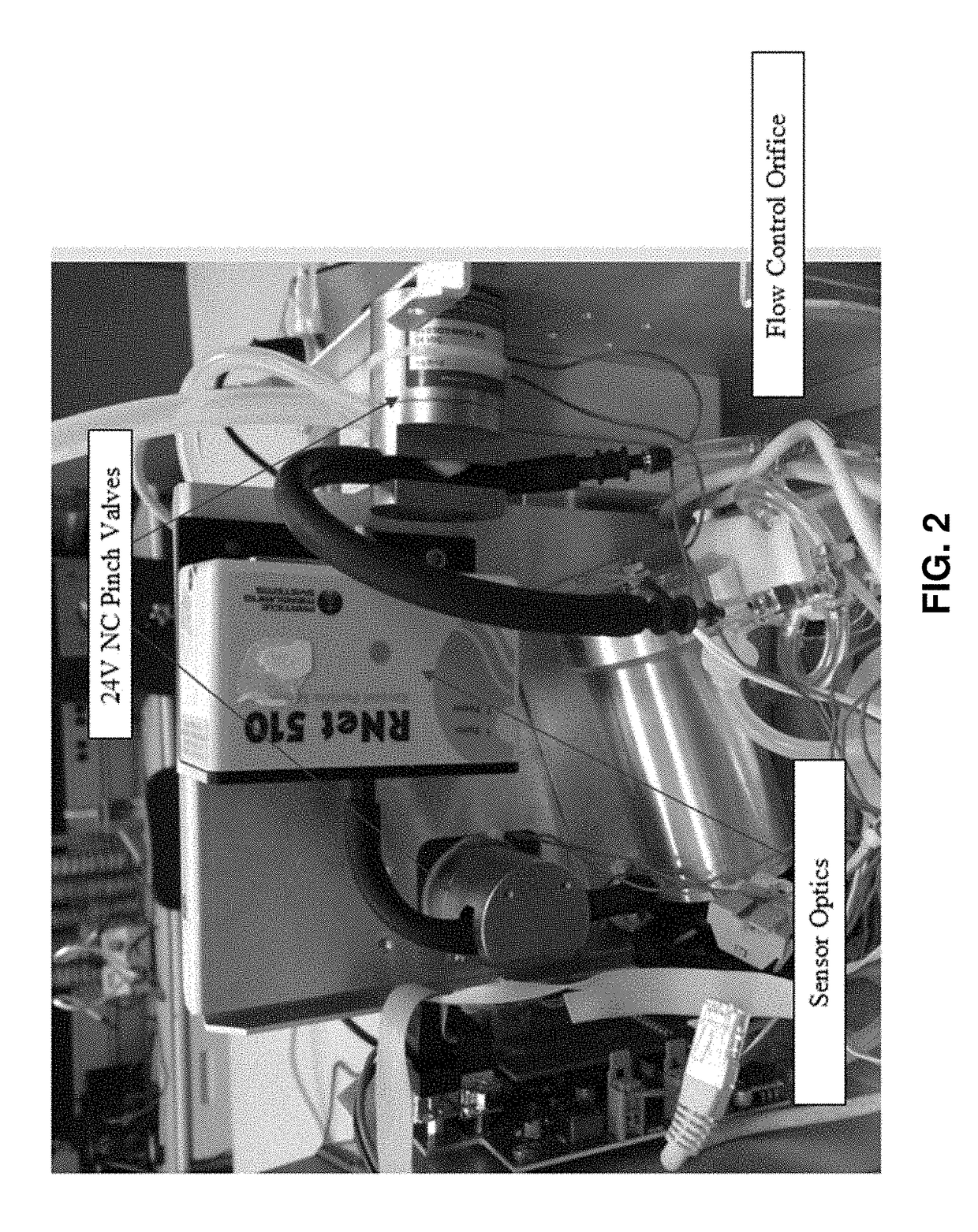
[0030]In an embodiment, the condensation isolation system is configured to automatically engage the isolation systems when the power of the condensation particle counter is off and is described in FIG. 1. Connecting the means of condensate isolation directly to the device power avoids user errors, in some embodiments, automatic shutting of the valves can occur when the vacuum pump is not providing suction or when the device is not in operation. Once power is connected to the device and the power switch is turned on the isolation valves open and allow the sample to flow through the system. FIG. 1 illustrates pinch valves, but embodiments may employ any valve type such as ball valves, check valves, needle valves, diaphragm valves or popper valves. A passive system where the default condition closes the isolation valve(s) will ensure that anytime the device is shipped or transported a significant distance the valves are closed and condensate ...


PUM

PropertyMeasurementUnit
sizeaaaaaaaaaa
sizeaaaaaaaaaa
sizeaaaaaaaaaa

Abstract

The systems and methods provided herein relate generally to the prevention of migration of condensate in a condensation particle counter between components designed to handle condensate (e.g. saturator, condenser, condensate reservoir) and components which may be damaged by the condensate (e.g. detection and flow control devices).

Description

CROSS-REFERENCE TO RELATED APPLICATIONS[0001]This application claims priority to and the benefit of U.S. Provisional Patent Application No. 62 / 345,572 filed Jun. 3, 2016, which is hereby incorporated by reference in its entirety to the extent not inconsistent herewith.BACKGROUND OF INVENTION[0002]This invention is in the field of condensation particle counters or condensation nuclei counters. In an embodiment, provided herein are systems and methods that prevent the migration of condensate from components of the system designed to contain condensate (e.g. condensate reservoir, saturator, or condenser) to components which may be damaged or interfered with by the presence of a condensate (e.g. particle counters, optical components of an optical particle counter, and flow control devices such as orifices).[0003]A large portion of the micro-contamination industry and clean manufacturing industries is reliant on the use of particle counters, such as are described in a number of U.S. Pate...

Claims


Application Information

Patent Timeline
Patent Type & Authority Patents(United States)
IPC IPC(8): G01N1/00G01N15/06G01N15/00G01N15/14
CPCG01N15/065G01N2015/1486G01N2015/03
Inventor KNOLLENBERG, BRIANPAVONE, STEPHENKETCHAM, CLIFFTHOMPSON, REBECCA
Owner PARTICLE MEASURING SYST
Learn More