

Laser spot tracking receiver
- Summary
- Abstract
- Description
- Claims
- Application Information
AI Technical Summary
Benefits of technology
Problems solved by technology
Method used
Image

Examples
Embodiment Construction
[0009]The term “hot spot” refers to effects that reduce the stability and accuracy of the centroid of the spot of the reflected laser light received by a weapon's seeker head. The effects may be due to irregularities in the reflected beam and / or irregularities on the seeker head, and may include, for example vignetting, smudges on the lens of the seeker head, dirt on the lens of the seeker head, and low energy spots in the collected optical energy.
[0010]In U.S. Pat. No. 8,451,432, the inventors of the present invention provided a system which defocuses the received laser beam, splits the beam into two different beams, and directs each defocused beams toward respective detectors. The data from both detectors is processed to cancel or diminish effects of hot spots.
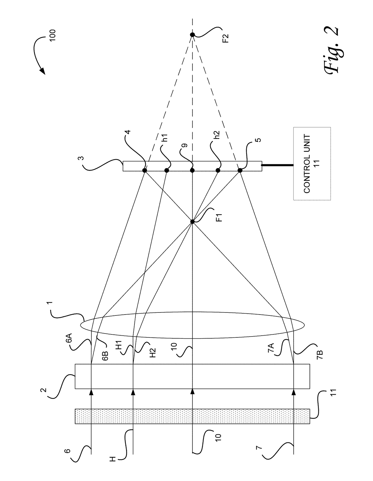
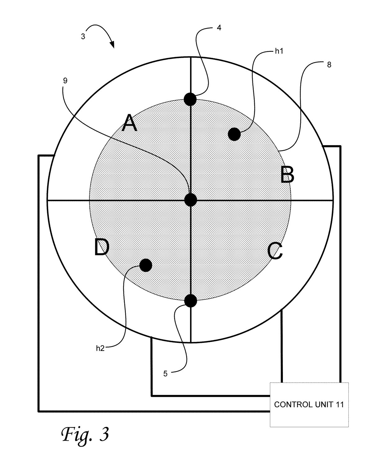
[0011]In order to provide a more robust technique for diminishing hot spot effects, the present invention uses a bifocal element for creating two beam sets, and a single detector for receiving the two beam sets. The effects ...
PUM
 Abstract
Description
Claims
Application Information