
Surgical handpiece with disposable concentric lumen work tip

a surgical handpiece and work tip technology, applied in the field of ultrasonic surgical handpieces with work tips, can solve the problems of increasing the cost of each procedure, insufficient simple autoclaving, and limited sterilization to those parts

Active Publication Date: 2019-02-19
SURGICAL DESIGN
View PDF21 Cites 3 Cited by
  • Summary
  • Abstract
  • Description
  • Claims
  • Application Information

AI Technical Summary

Benefits of technology

The present invention provides a new type of surgical handpiece which has specific technical effects. These effects include improved efficiency, better cooling, and a more compact design. The handpiece includes a work tip that is designed to perform various surgical procedures. The work tip can be used alone or in conjunction with a sleeve to create a more complex and specialized tool for surgeries. Overall, this new handpiece offers better performance and reliability for surgeons and their patients.

Problems solved by technology

One time consuming procedure is the sterilization of the handpiece between surgeries on different patients.
If the aspiration channel only extends through the work tip and connecting body, sterilization can be limited to those parts.
Simple autoclaving may be insufficient to eliminate possibility of spreading this disease because it is viable up to about 1100° F. Certain detergent washes have to be employed for this purpose.
However, the portion of the housing surrounding the work tip and which forms the chamber for irrigation fluid, also needs to be replaced in this design.
Thus, while the speed of treating patients can be increased by using a handpiece with disposable parts, the cost for each procedure increases because new parts are required for each patient.

Method used


Image

  • Surgical handpiece with disposable concentric lumen work tip
  • Surgical handpiece with disposable concentric lumen work tip
  • Surgical handpiece with disposable concentric lumen work tip

Examples


Embodiment Construction

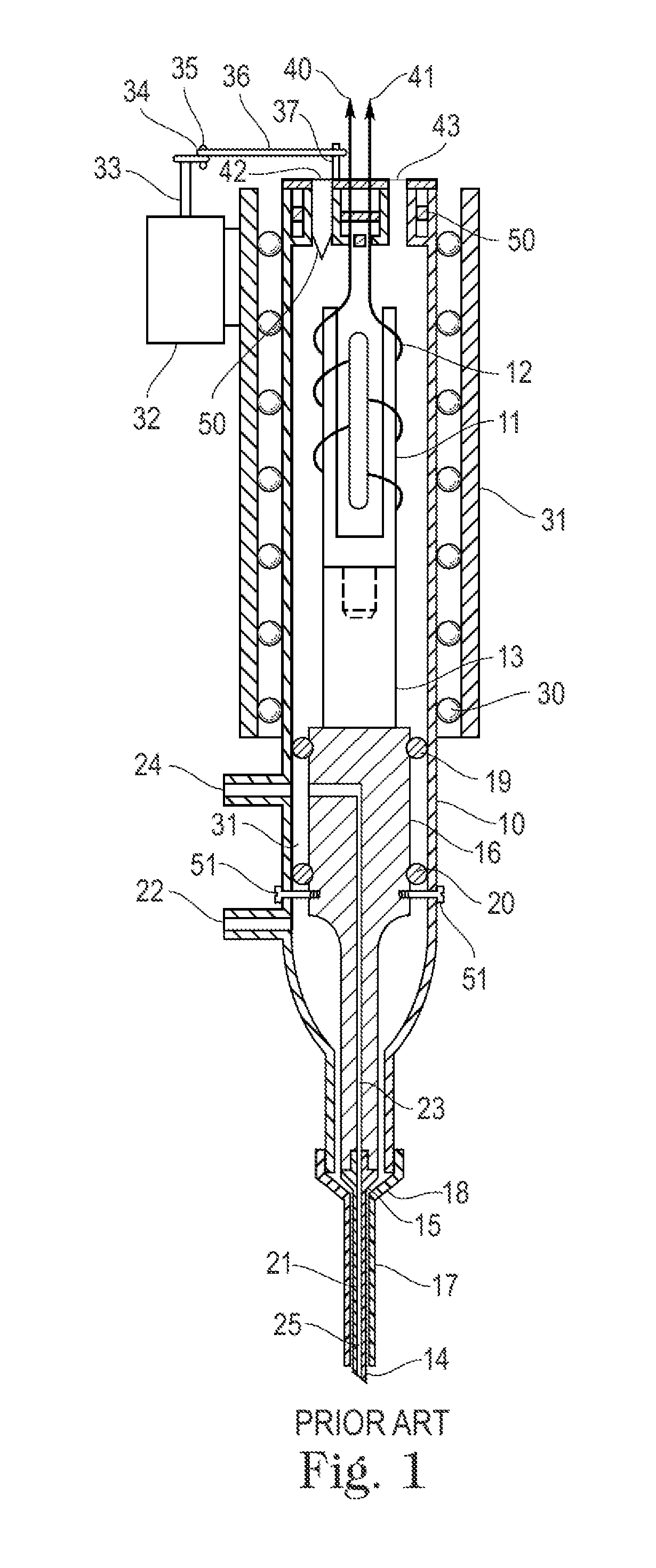
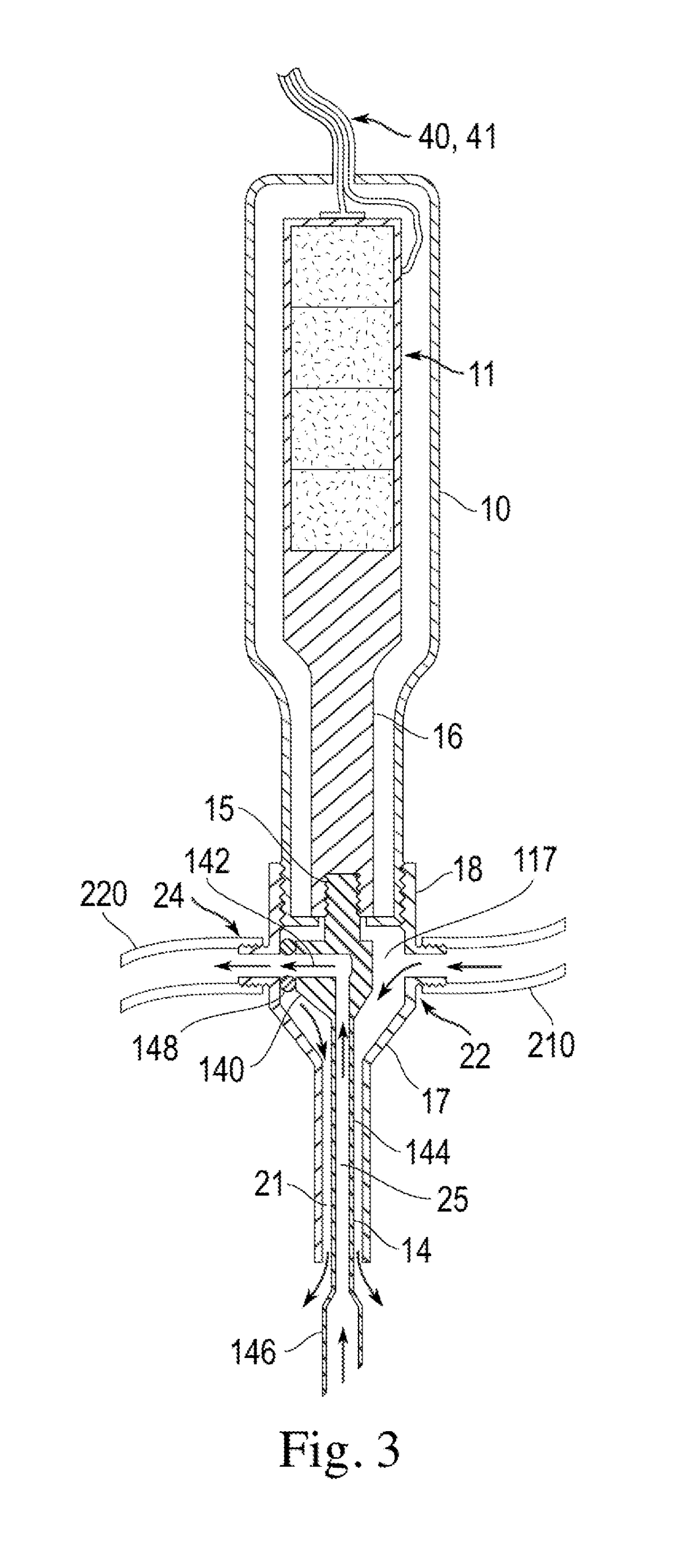
[0034]FIG. 3 shows an embodiment of the handpiece of the invention. It uses a number of the components of the prior art type of handpiece described above with respect to FIG. 1. The source of the electro-mechanical energy is shown schematically as transducer 11. This transducer can be either the electromagnetic type or the piezoelectric crystal type. It is preferred, and is conventional, that the output power of the transducer 11 is controlled by electrical signals delivered over wires 40, 41 from a control unit (not shown). These signals allow the ultrasonic power at the work tip distal end to be varied as needed by the surgeon.

[0035]Connected to the transducer 11 is the connecting body 16. Both the transducer 11 and connecting body 16 are provided in a housing 10. Although not shown for the sake of clarity, the transducer and connecting body are suspended within housing 10 so as to permit the longitudinal vibration of the transducer and connecting body to occur relative to the hou...


PUM


Abstract

A surgical handpiece has a connecting body with a distal end and a work tip with a hub at a proximal end. The hub is detachably connected to the connecting body by a threaded connector. The work tip has an open operating end at a distal end. This opening leads an axial channel extending through the work tip from the operating end to the hub. A radial channel extends from the axial channel in the hub to the external surface of the hub. A sleeve surrounds and is spaced from the hub. This sleeve extends to the vicinity of the operating end of the work tip, and has a first external connector in the region of the radial channel of the hub. The sleeve also has a second external connector. A seal is provided for establishing a fluid connection between the radial channel of the hub and the second external connector of the sleeve. The first external connector of the sleeve is in fluid connection with an irrigation channel between the inner surface of the sleeve and the external surface of the work tip. This irrigation channel extends to the vicinity of the operating end of the work tip for delivery of irrigation fluid to that area. The irrigation channel is generally concentric with the axial channel in the hub. Aspiration fluid is withdrawn from the open operating end of the work tip, through the axial and radial channels of the hub, the seal and the second external connector of the sleeve to an aspiration pump.

Description

CROSS-REFERENCE TO RELATED APPLICATIONS[0001]The present application is a continuation-in-part of prior U.S. patent application Ser. No. 14 / 292,459 filed on May 30, 2014, which is a continuation-in-part of U.S. patent application Ser. No. 14 / 142,555 filed on Dec. 27, 2013, which in turn is a continuation-in-part of prior U.S. patent application Ser. No. 12 / 215,315 filed on Jun. 26, 2008 (now U.S. Pat. No. 8,641,658, which issued Feb. 4, 2014). Priority is claimed only to U.S. patent application Ser. No. 14 / 292,459 filed on May 30, 2014, and U.S. patent application Ser. No. 14 / 142,555 filed on Dec. 27, 2013, both of which are incorporated herein in their entirety.TECHNICAL FIELD[0002]The present invention is generally directed to an ultrasonic surgical handpiece with a work tip that is disposable, and can be used for various types of surgery, e.g., the removal of cataracts from the eye of a patient by phacoemulsification.BACKGROUND OF THE INVENTION[0003]The use of ultrasonic and lase...

Claims


Application Information

Patent Timeline
Patent Type & Authority Patents(United States)
IPC IPC(8): A61M3/02A61F9/008A61M1/00A61F9/007A61B17/32A61B18/26
CPCA61M3/0283A61F9/008A61F9/00745A61M1/0064A61B2017/320084A61M2210/0612A61B2217/005A61B2217/007A61F2009/0087A61F2009/00887A61B2018/263A61M1/774
Inventor BANKO, WILLIAM
Owner SURGICAL DESIGN
Learn More