
Static discharger, aircraft and installation process for the static discharger

a technology of static discharger and installation process, which is applied in the installation of lighting conductors, aircraft lighting protectors, electric cable installations, etc., can solve the problems of increased weight, inconvenient installation, complex installation, etc., and achieves the effect of increasing the universality of static discharger, increasing weight, and complex assembly

Active Publication Date: 2019-02-19
AIRBUS BEIJING ENG CENT
View PDF8 Cites 1 Cited by
  • Summary
  • Abstract
  • Description
  • Claims
  • Application Information

AI Technical Summary

Benefits of technology

The present invention provides a static discharger that can be adjusted and positioned accurately with respect to a trailing edge profile member, even if it is narrow. This is achieved through the use of indexing mechanisms and scales that enable easy identification of the discharging portion in relation to the basement and the rudder / elevator. The discharger body is then positioned based on the determined angle to ensure it is installed in line with the flight direction.

Problems solved by technology

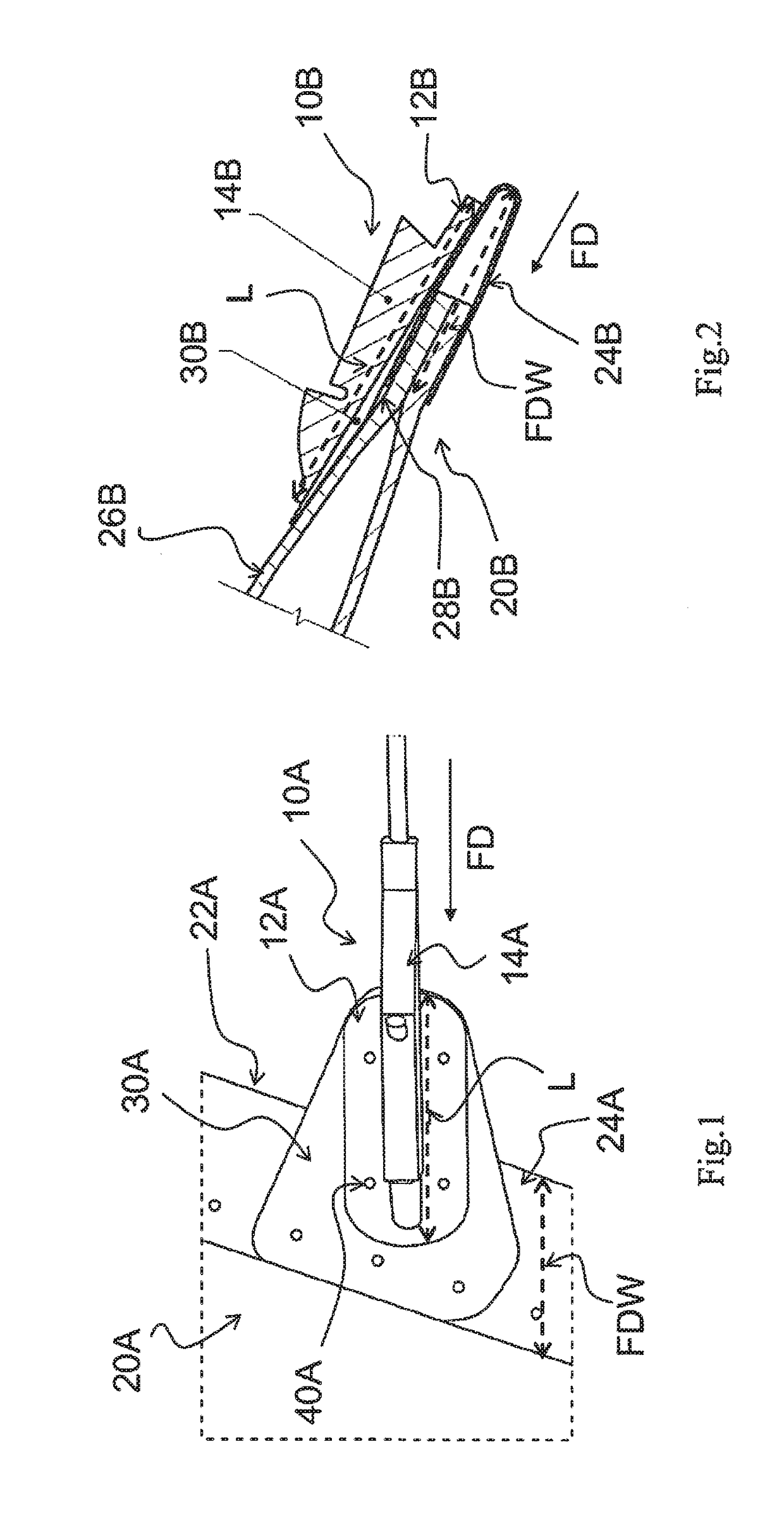
In addition, the partially suspended installations of the metallic plate 30A and the basement 12A may also affect the aerodynamic surface (which will cause turbulence effect) and cause inconvenient installation.
In this way, in the static discharger 10B according to the relevant technology, similarly, since an additional metallic plate 30B is needed for the installation, the weight is increased, the installation is complex, and the aerodynamic surface is affected.
On the other hand, in the static discharger 10A and the static discharger 10B according to the relevant technology, since there is no an indexing mechanism (dividing mechanism), conveniently and accurately adjusting and determining the angle of the discharging portion with respect to the basement and to the rudder / elevator (the trailing edge profile member) cannot be achieved, and thus it is difficulty to ensure that the discharging portion is installed in line with the flight direction.

Method used


Image

  • Static discharger, aircraft and installation process for the static discharger
  • Static discharger, aircraft and installation process for the static discharger
  • Static discharger, aircraft and installation process for the static discharger

Examples


Embodiment Construction

[0043]Hereinafter, the present invention will be described in detail with reference to the drawings and in conjunction with the exemplary embodiments. The following detailed description is for illustration purpose only but is not intended to limit the present invention and its application or usage.

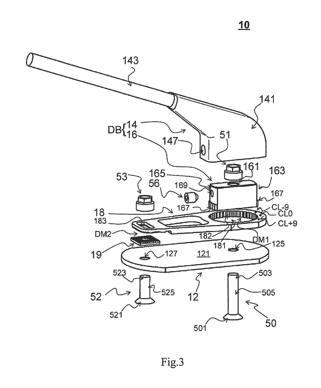
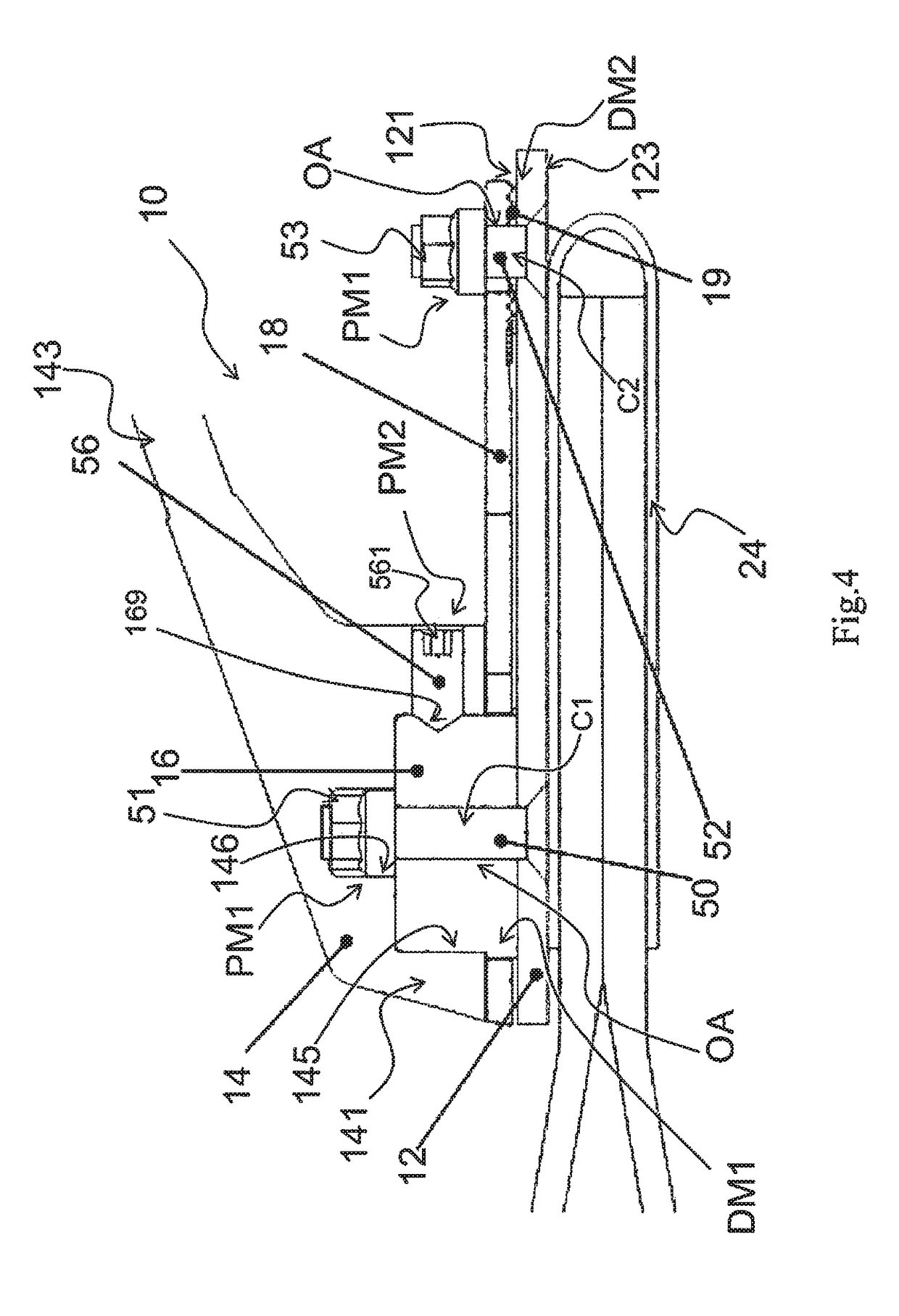
[0044]Firstly, a static discharger 10 according to an exemplary embodiment of the present invention is described with reference to FIG. 3 and FIG. 4. FIG. 3 is an exploded perspective view showing a static discharger according to an exemplary embodiment of the present invention, and FIG. 4 is a longitudinal section view showing a static discharger according to an exemplary embodiment of the present invention.

[0045]As shown FIG. 3, the static discharger 10 may include a basement discharging portion 14, an internal-media 16, a locking plate 18 (serving as an intermediate body according to the present invention) and a serration plate 19. It is to be noted herein that the assembly of the disch...


PUM


Abstract

The present invention relates to a static discharger, an aircraft, and an installation process for the static discharger. According to an aspect of the present invention, a static discharger is provided which includes: a basement; and a discharger body installed to the basement. An installation orientation adjusting mechanism is provided between the basement and the discharger body, and the installation orientation adjusting mechanism allows the discharger body to be rotationally orientated, with respect to the basement, to a predetermined installation orientation during an on-site-installation of the static discharger. The static discharger further includes a first fixing mechanism adapted to fix the discharger body, which has been oriented to the predetermined installation orientation, to the basement. According to the present invention, for example, installation adaptation and universality of the static discharger and adjustment and determination of installation orientation of the static discharger can be improved.

Description

RELATED APPLICATIONS[0001]This application claims priority to Chinese Patent Application No. 201510111311.X, filed Mar. 13, 2015, which is incorporated by reference in its entirety herein.FIELD OF THE INVENTION[0002]The present invention relates to a static discharger, an aircraft having the same, and an installation process for the same, and more particularly to a static discharger improved in aspects of, for example, installation adaptation and universality, adjustment and determination of installation orientation, and so on.BACKGROUND OF THE INVENTION[0003]Generally, high-speed moving bodies such as the airplane, the aerospace plane, the train and the automobile are provided with a static discharger. In particular, the static discharger is an essential component in the airplane used to protect relevant structures of the airplane by discharging the current (static electricity) to the air slowly. The static discharger may be installed at the wing (for example, a trailing edge of th...

Claims


Application Information

Patent Timeline
Patent Type & Authority Patents(United States)
IPC IPC(8): B64D45/02H02G13/00H05F3/02
CPCB64D45/02H05F3/02H02G13/80
Inventor WANG, LONGHAN, ZENGLI
Owner AIRBUS BEIJING ENG CENT
Learn More