Adjustable spacer with hardened ends

a technology of hardened ends and spacers, which is applied in the direction of heat treatment equipment, instruments, furniture, etc., can solve the problems of excessive and premature wear of bearings, tires, drive or wheel end failure, and race, especially those mounted on heavy-duty trucks or similar vehicles, and achieve the effect of resisting wear

Active Publication Date: 2019-02-19
TEMPER
View PDF21 Cites 2 Cited by
  • Summary
  • Abstract
  • Description
  • Claims
  • Application Information

AI Technical Summary

Benefits of technology

[0008]The first end portion includes a face exposed in an axial direction, which may be initially formed of hardened material or surface hardened. The level of hardness of the end portions may be at HRC 62 or harder. The second end portion also includes a face exposed in an axial direction, which may be initially formed of hardened material or surface hardened. The annular spacer is generally configured to be assembled on a shaft including an axle or spindle between two roller bearings to apply a force axially on the roller bearings. The hardened material, which contacts the face of the roller bearing helps resists wear. Also, the deformability of the intermediate section of the spacer allows the same to be compressed in the axial direction, if needed, to maintain the desired force on the bearing face to also help resist crawl and if crawl does occur to resist wear. The spacer may be a constant force spacer where the intermediate portion is compressible at a constant force over a substantial distance of compressibility.

Problems solved by technology

However, bearings, particularly those mounted on heavy duty trucks or similar vehicles may be exposed to large forces when mounted in a bearing assembly.
Sometimes, such mounted bearings may crawl, namely, rotate, or move relative to the axle or spindle, which is undesirable.
Movement of the inner race in this situation may lead to excessive and premature wear of the race, shaft and / or bearing assembly in general, as well as the tires.
This in turn may lead to, for example, drive or wheel end failure and a catastrophic event.
However, when such a spacer is used, any bearing crawl may also result in additional damage or wear on the bearing and / or spacer at their area of contact, for example, between the axially directed face of the bearing and face of the spacer.
In addition to the aforementioned problems, shafts and bearing assemblies may also have a variable diameter.

Method used


Image

  • Adjustable spacer with hardened ends
  • Adjustable spacer with hardened ends
  • Adjustable spacer with hardened ends

Examples


Embodiment Construction

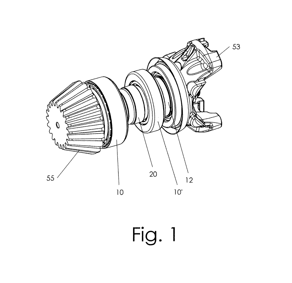
[0023]Referring to FIG. 1, a common truck drive assembly is shown. However, the invention is useable on bearing assemblies mounted on other types of shafts such as wheel axles and spindles. As shown in FIG. 1, the drive system includes a rotating shaft such as a drive shaft 12 and a pair of oppositely opposed bearings 10, 10′ mounted thereon. An adjustable spacer 20 constructed in accordance with the principles of the present invention is mounted therebetween. A first end 55 of the shaft includes a gear which drives another gear (not shown) to rotate, for example, a wheel or other shaft. A yoke 53, for example, on the opposite end of the shaft 12 is connected to, for example, another rotating element (not shown) to drive the shaft 12.

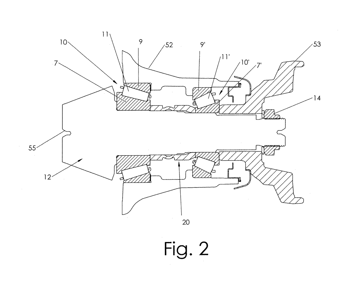
[0024]Referring to FIG. 2, for simplicity a sectional schematic view of the drive system of FIG. 1 is shown. The assembly includes a lock nut 14 used to secure a bearing assembly between a housing 52 (such as a power transmission housing) and a shaft 12...


PUM

PropertyMeasurementUnit
temperatureaaaaaaaaaa
forceaaaaaaaaaa
inner diameteraaaaaaaaaa

Abstract

An adjustable spacer with hardened end portions and a non-hardened intermediate portion therebetween is mountable between a pair of roller bearings also mounted on a shaft such an axle or spindle or the like. The hardened material contacts the faces of the roller bearings but helps prevent wear therebetween and unwanted movement of the bearings on the shaft. The unhardened material allows the spacer to collapse in the axial direction to maintain desired axial loads on the bearings.

Description

TECHNICAL FIELD[0001]This invention relates in general to the field of shaft mounted bearings, and in particular, to an adjustable spacer with hardened end portions useable between a pair of bearings mounted on a shaft including an axle or spindle or the like.BACKGROUND ART[0002]A typical tapered roller bearing may include a bearing cone having an inner bearing race, a plurality of rollers within a roller cage, and an outer bearing race. Typically, a pair of tapered roller bearings, may be mounted on a wheel axle for rotation of the wheel. In addition, they may be mounted on drive systems used to drive, for example, wheels. However, bearings, particularly those mounted on heavy duty trucks or similar vehicles may be exposed to large forces when mounted in a bearing assembly. The inner bearing race of a bearing used in an assembly is generally designed to remain stationary relative to the shaft upon which it is mounted, such that the outer race rotates relative to the inner race via ...

Claims


Application Information

Patent Timeline
Patent Type & Authority Patents(United States)
IPC IPC(8): F16C25/06F16C19/36C21D1/42F16B31/04F16C25/08C21D1/10C21D9/00B21D53/12G01B5/14C21D1/63
CPCF16C25/086F16B31/04F16C19/364C21D1/42C21D1/10B21D53/12C21D9/0068F05D2300/171G01B5/146C21D1/63F16C2229/00F16C2361/61F16C35/063F16C19/547Y02P10/25
Inventor RODE, JOHN E.
Owner TEMPER
Why Eureka
Try Eureka