
Constrained acetabular liner

a technology of acetabular liner and acetabular cup, which is applied in the direction of acetabular cup, hip joint, joint implant, etc., can solve the problems of affecting the stability of the hip, and still a high incidence of repeated dislocation

Pending Publication Date: 2022-11-03
THE FEINSTEIN INST FOR MEDICAL RES
View PDF0 Cites 0 Cited by
  • Summary
  • Abstract
  • Description
  • Claims
  • Application Information

AI Technical Summary

Benefits of technology

The solution effectively prevents dislocation by providing a stable and durable coupling mechanism, reducing the need for revision surgeries and improving the longevity of the THR prosthesis, while maintaining compatibility with standard femoral components and minimizing surgical complexity.

Problems solved by technology

Even for those patients who are successfully reduced and sent home, however, there is still a high incidence of repeated dislocations.
Several problems may develop in THRs stabilized by the pseudo-capsule and the patient's musculature.
With time the pseudo-capsule may stretch, allowing the femoral ball to move away from the acetabulum making the hip less stable so that a minor trauma can cause a dislocation.
Muscles may weaken due to other medical conditions and as the patient ages.
Even with a very stable THR, a fall or accident can cause dislocation.
Once dislocation happens, the pseudo-capsule may be torn.
In some cases, this may lead to a defect in the capsule that does not close.
Several problems are associated with dual mobility THR prostheses.
Since the acetabular shell and the liner are both metallic, cyclical loading of the joint may lead to spalling, fretting, corrosion, and erosion of the metal surfaces.
The joint may fail as a result of wearing down of these surfaces.
In addition, the worn metal surfaces may release of metal ions into the surrounding tissue.
This may cause increased wear, potentially causing the joint to fail.
Fenestrations in the liner can lead to areas of stress concentration, which may lead to fatigue and breakage when the prosthesis is subjected to cyclical loading caused by the patient's body movement.
A problem with this design is that a relatively small overlap of the liner and ball is provided to constrain the ball in the liner.
The cup liner is not compatible with femoral balls made according to industry standard dimensions.

Method used


Image

  • Constrained acetabular liner
  • Constrained acetabular liner
  • Constrained acetabular liner

Examples


Embodiment Construction

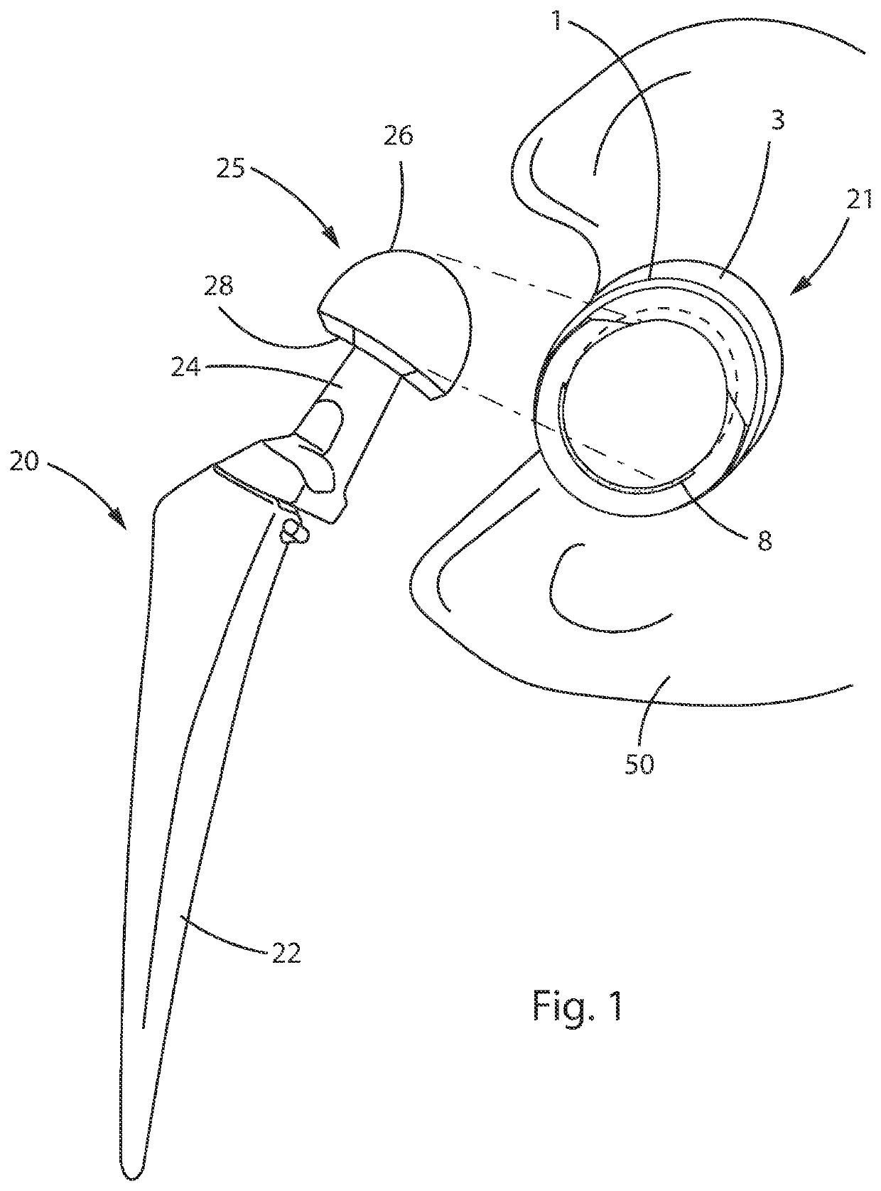
[0031]FIG. 1 is a perspective view of the components of a THR prosthesis according to an embodiment of the disclosure. A femoral component 20 includes a femoral stem 22. At the top of the femoral component 20, that is, the superior end when implanted in a patient, there is a femoral ball 25. The ball has a constant diameter surface 26 that terminates in a planar shoulder 28. Femoral neck 24 connects the femoral ball 25 with the stem 22. According to one embodiment, the constant diameter portion of femoral ball 25 has a diameter of 36 mm. The distance from the planar surface 28 and the farthest extension of surface 26 is 30 mm. These dimensions are provided for purposes of illustration. Other sized femoral components can be used within the scope of the disclosure, provided the appropriate size modifications are made to the acetabular component as will be explained below.

[0032]An acetabular cup component 21 couples with the femoral component 20. The cup 21 is formed from an anchor por...


PUM


Abstract

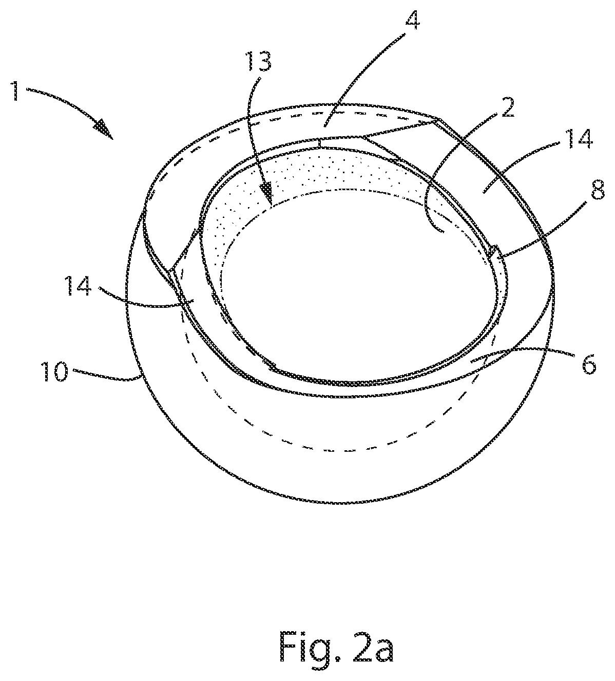
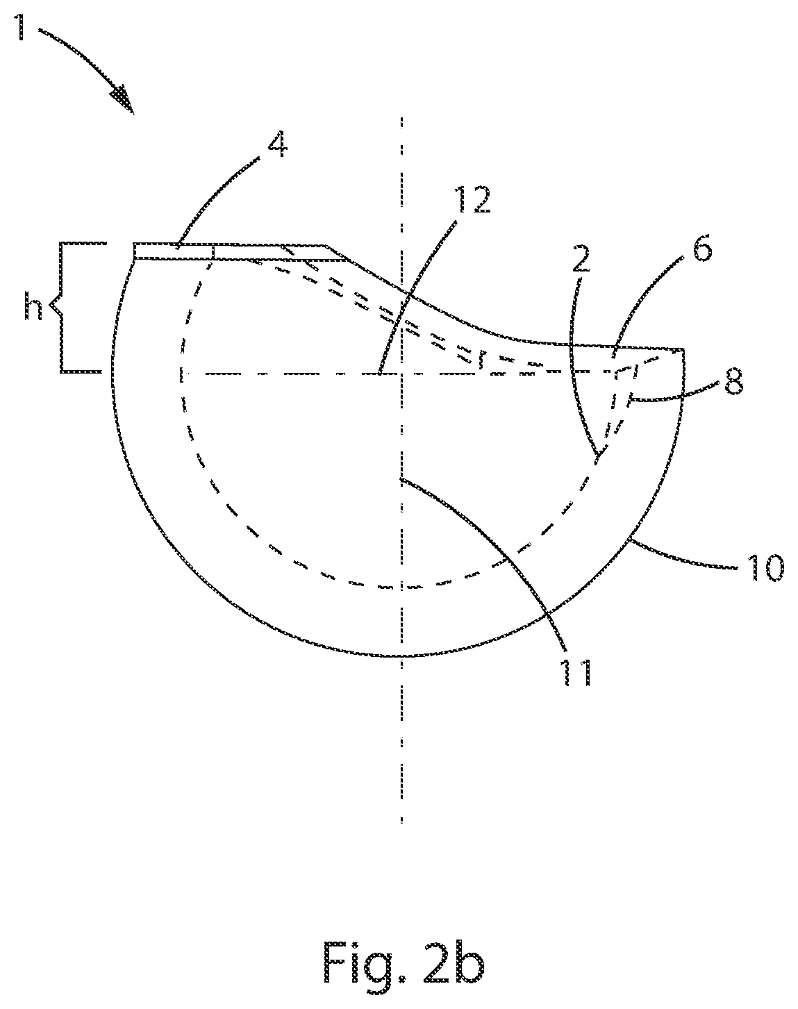
There is provided an acetabular cup liner for a total hip replacement (THR) prosthesis comprising an inner surface with a hemispherical portion having a radius of curvature. The hemispherical portion is disposed about a centerline and it intersects a hemisphere plane perpendicular to the centerline so that the intersection of the hemispherical portion and the plane define a circle having a radius equal to the radius of curvature. The liner further comprises a capture portion continuous with the hemispherical portion that has the same radius of curvature as the hemispherical portion and connects with the hemispherical portion at the hemispherical plane along a first arc of the circle on the plane, and extends a first distance out of the plane. The liner further comprises an insertion portion continuous with the hemispherical portion. The insertion region is connected with the hemispherical portion along a second arc of the circle on the plane. The distance from the centerline to the insertion portion is greater than the radius. The cup liner constrains the femoral ball portion of the THR prosthesis. The femoral ball portion is engaged with the liner by orienting the ball at an angle so that the shoulder portion of the ball aligns with the insertion portion, pressing the ball into the liner, and orienting the ball away from the angle.

Description

[0001]This application claims priority under 35 U.S.C. § 119 to U.S. Provisional Patent Application No. 62 / 864,240, filed on Jun. 20, 2019. This application is a continuation of co-pending U.S. patent application Ser. No. 16 / 903,991, filed Jun. 17, 2020. The disclosure of each of these applications is incorporated herein by reference.BACKGROUNDField[0002]The present application relates to acetabular cups and combinations of femoral stem components and acetabular cups for total hip replacement. In particular, the present disclosure relates to an acetabular cup that forms a stable coupling with the femoral ball coupled with a femoral stem that is resistant to dislocation.Description of the Related Art[0003]Total Hip Replacement (THR) is a common medical procedure to repair damage to a patient's pelvis and / or femur due to trauma or degenerative disease. A prosthetic joint is implanted to replace the patient's natural joint. One side of the THR joint is formed by an acetabular cup lined...

Claims


Application Information

Patent Timeline
Patent Type & Authority Applications(United States)
IPC IPC(8): A61F2/34A61F2/46A61F2/36
CPCA61F2/34A61F2/4609A61F2/3609A61F2002/3654A61F2002/349A61F2/32A61F2002/3443A61F2002/365
Inventor ASNIS, STANLEYGOLDSTEIN, TODD
Owner THE FEINSTEIN INST FOR MEDICAL RES
Learn More