Charged particle beam device, optical device, irradiation method, diffraction grating system, and diffraction grating

a charge particle and beam technology, applied in the field of light beams, to achieve the effect of efficient observation, processing and energy transfer

Active Publication Date: 2019-02-19
HITACHI LTD
View PDF3 Cites 1 Cited by
  • Summary
  • Abstract
  • Description
  • Claims
  • Application Information

AI Technical Summary

Benefits of technology

[0027]By using the present invention, it is possible to generate spiral waves of a certain shape, or spiral waves capable of transmitting momentum in a certain direction. Further, it is possible to provide an apparatus and a method using efficient observation, processing and energy transfer using the spiral waves.

Problems solved by technology

Especially, in the magnetization observation, the electron beam has a fundamental disadvantage with no sensitivity for parallel magnetization to the direction of propagation, but there is a possibility of observing the magnetization of the electron beam in a propagation direction in the electron spiral wave.

Method used


Image

  • Charged particle beam device, optical device, irradiation method, diffraction grating system, and diffraction grating
  • Charged particle beam device, optical device, irradiation method, diffraction grating system, and diffraction grating
  • Charged particle beam device, optical device, irradiation method, diffraction grating system, and diffraction grating

Examples


example 1

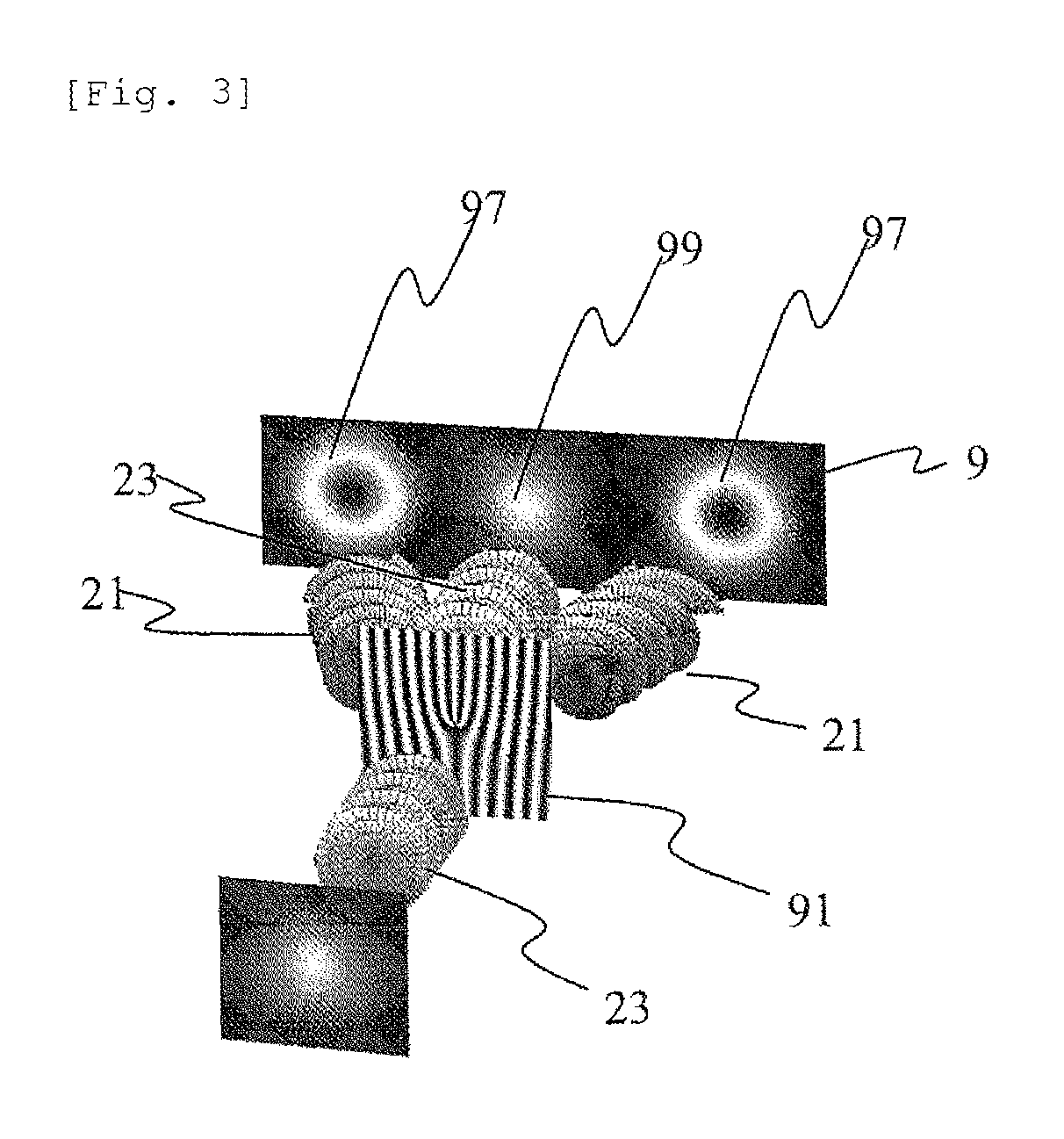
[0080]Example 1 for implementing the present invention is illustrated in FIG. 8. It has a configuration different from that illustrated in FIG. 3, and a diffraction grating 91 including the edge dislocation is irradiated with a plane wave 23 passes through the diffraction grating and thereafter forms a spiral wave 21 as a diffraction wave. However, the opening shape 81 of the diffraction grating 91 including the edge dislocation has a shape as an arrowhead (hereinafter, referred to as an arrowhead shape), and as illustrated in FIGS. 7a-7e, the arrowhead shape is reflected in the shape of annular diffraction spots 97. Moreover, the shape is a diffraction pattern in which annular diffraction spots 97 are rotated (here, rotated by 90 degree) to the left and right of the orientation indicating the diffraction spot 99 of a transmitted wave is in clock / counter clockwise directions respectively.

[0081]It is possible to make a predetermined spiral wave 21 by spatially separating one of the a...

example 2

[0085]Example 2 for implementing the present invention will be described with reference to FIG. 11A and FIG. 11B. FIG. 11A is an example of a diffraction grating system in which the diffraction grating 91 and the opener 83 are formed into a different structure. The opening shape 81 is a part of the opener 83. A state is illustrated in which the opener 83 is disposed adjacent to the upper part of the diffraction grating 91 (the grating outer shape is rectangular) with a third-order edge dislocation, but the upper and lower relationship between the diffraction grating and the opener, and the mutual distance are not limited to the configuration of FIGS. 11A and 11B. The relative positions of the diffraction grating and the opener may be changeable in the horizontal direction and the vertical direction. In other words, the positions of the diffraction grating 91 and the opener 83 may be changed.

[0086]FIG. 11B illustrates the shape without rotational symmetry (that is, having a single ro...

example 3

[0090]FIG. 12 illustrates Example 3 for implementing the present invention. FIG. 12 illustrates a case where a part of a closed curve defining the opening shape 81 of the opener 83 illustrated in FIG. 11 is irradiated with light beams or particle beams that irradiate a circular area. In the example of FIG. 12, the opening shape 81 of the light beams or the particle beams passing through the diffraction grating system becomes an irradiated area of the opening portion of the opener 83 as a result.

[0091]Accordingly, it is indicated that it is possible to realize the control equivalent to Example 2, not only by changing the shape of the opener 83, but also changing the irradiation area of the irradiation optical system and the irradiation intensity of the light beam or the particle beam (in other words, by deflecting the optical axis and converging beams by the lens).


PUM


Abstract

The outer shape and size of a diffraction grating including an edge dislocation is made smaller than the irradiation areas of light waves and electromagnetic waves, by using an opener different from in the diffraction grating, the shape and size of the opening is superposed on the shape of a spiral wave that is generated by an edge dislocation diffraction grating, and the shape and size of the opening are reflected in the shape and size of the spiral wave on the diffractive surface. In addition, not only a diffraction grating system including a pair of a single opener and a single diffraction grating, but also a diffraction grating system in which plural openers and plural edge dislocation diffraction gratings are combined are used, and plural spiral waves can be generated on the diffractive surface with a higher degree of freedom.

Description

TECHNICAL FIELD[0001]The present invention relates to light beams including X-rays, charged particle beams such as electron beams, neutron beams, and ion beams, or uncharged particle beams. The present invention relates to a fork-type diffraction grating that generates spiral waves of which an equiphase surface forms a spiral shape, a diffraction grating including an opener that defines the outer shape of the grating, a diffraction grating system, an optical apparatus or a particle beam apparatus with the diffraction grating system, and a diffraction method using them.BACKGROUND ART[0002]<1. Spiral Wave>[0003]Spiral waves which are the premise of the present application will be described, with light waves as an example. In a coherent optical system, the phase of propagating light waves is uniquely determined. A plane having an equal phase is called a wavefront, and waves are classified into plane waves (see FIG. 1a) or spherical waves depending on the shape of the wavefront.[0...

Claims


Application Information

Patent Timeline
Patent Type & Authority Patents(United States)
IPC IPC(8): G21K1/06H01J37/04H01J37/09H01J37/26G02B5/18
CPCG21K1/06G02B5/1842G02B5/1866H01J37/04H01J37/26H01J37/09G21K2201/067G02B2005/1804G21K2201/064
Inventor HARADA, KENKOHASHI, TERUOIWANE, TOMOHIRO
Owner HITACHI LTD
Why Eureka
Try Eureka