
Cost reduced synchronized-switching contactor

a contactor and synchronized switching technology, applied in the field of contactors, can solve the problems of requiring replacement of the contactor or the entire contactor, requiring replacement of the contactor surface, and high conductivity metals used at the surface of the contactor, so as to save the cost of conductive metal, reduce the arcing, and no additional hardware costs

Active Publication Date: 2019-02-19
SCHNEIDER ELECTRIC USA INC
View PDF10 Cites 0 Cited by
  • Summary
  • Abstract
  • Description
  • Claims
  • Application Information

AI Technical Summary

Benefits of technology

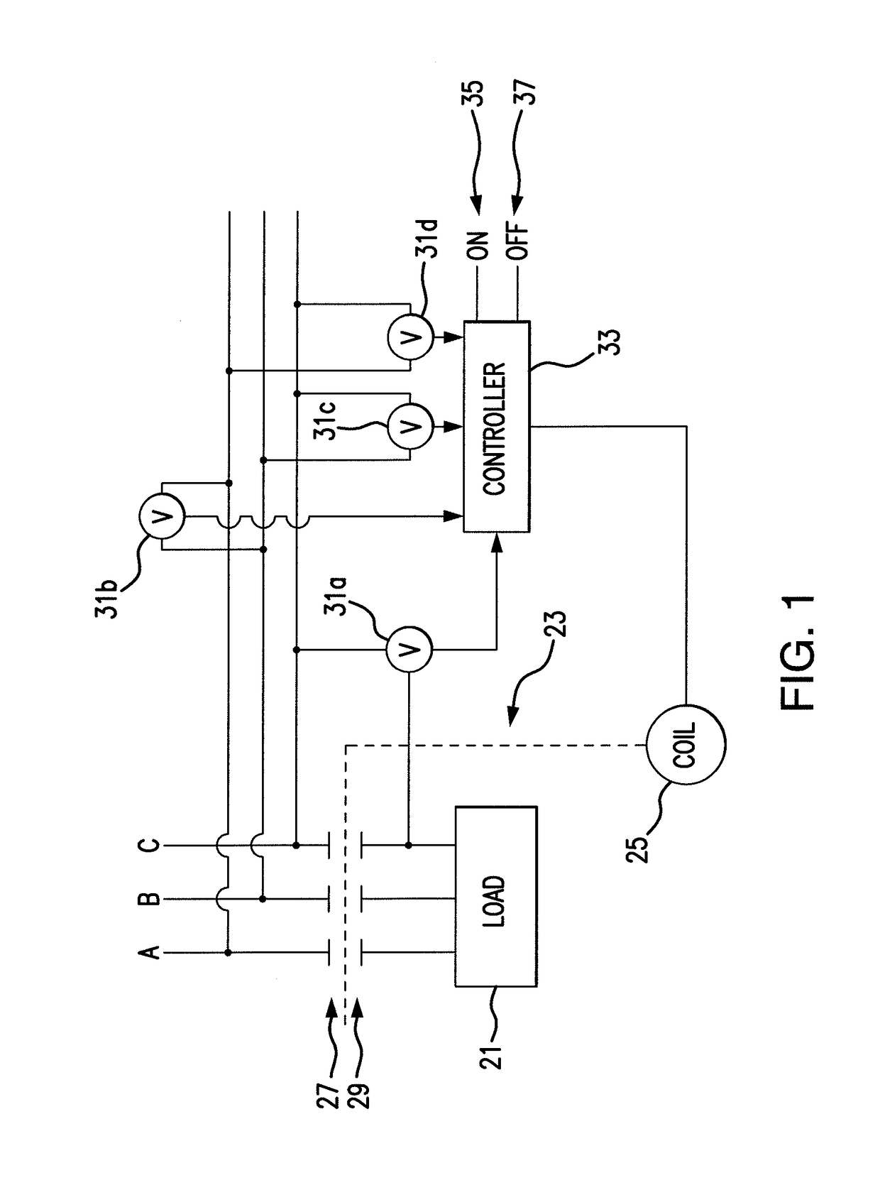
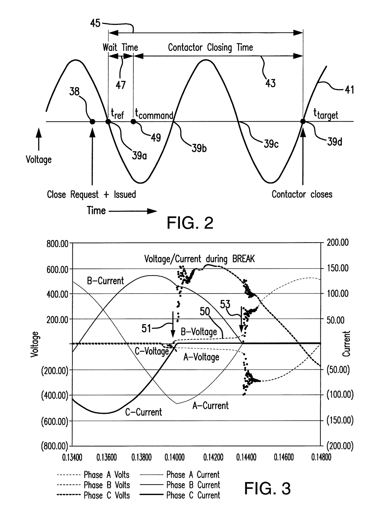
The invention is a method for controlling a three-phase motor contactor using a coil to change the position of the contacts. The method uses voltage monitoring to determine the best time to open or close the contacts, reducing arcing and saving energy. This is done by calculating the delay of the contactor and using it to synchronize the operation of the contacts at low power. The method also spreads the wear over each set of contacts to use precious metal more efficiently. Overall, the method is simple, economical, and effective in reducing arc energy.

Problems solved by technology

Arcing at the contacts upon their separation or closure will erode the expensive, high conductivity metals used at the surfaces of the contacts and may eventually require replacement of the contacts or the entire contactor mechanism.
But, the monitoring of the current involves the provision of current transformers (CTs), which are expensive in terms of money and physical space within the equipment.

Method used


Image

  • Cost reduced synchronized-switching contactor
  • Cost reduced synchronized-switching contactor

Examples


Embodiment Construction

[0013]As an initial matter, it will be appreciated that the development of an actual commercial application incorporating aspects of the disclosed embodiments will require many implementation specific decisions to achieve the developer's ultimate goal for the commercial embodiment. Such implementation specific decisions may include, and likely are not limited to, compliance with system related, business related, government related and other constraints, which may vary by specific implementation, location and from time to time. While a developer's efforts might be complex and time consuming in an absolute sense, such efforts would nevertheless be a routine undertaking for those of skill in this art having the benefit of this disclosure.

[0014]It should also be understood that the embodiments disclosed and taught herein are susceptible to numerous and various modifications and alternative forms. Thus, the use of a singular term, such as, but not limited to, “a” and the like, is not int...


PUM


Abstract

A simple, economically efficient, synchronized switching system for control of a three phase motor contactor utilizes only Voltage monitoring to determine zero crossings and knowledge of the sinusoidal power waveforms and operational delay period of the contactor, to synchronize operation of the contacts at low power. The phases can be serially utilized for zero crossing detection upon Close or Open commands, so as to spread the wear over each set of contacts. Expensive metal at the contact surfaces can therefore be used more efficiently. For arc energy reduction upon contact opening, knowledge of Line-Load Voltage on at least one phase can be used to derive an empirical determination of the voltage angle at opening which yields the lowest arc energy.

Description

BACKGROUND OF THE INVENTION[0001]1. Field of the Invention[0002]The present invention relates to the field of contactors and specifically to contactor actuation timing.[0003]2. Discussion of Related Art[0004]A “contactor” is an electrically controlled switch used for switching an electrical power circuit, similar to a relay except with higher current ratings. An electromagnetic ‘actuator’ is typically that part of the contactor mechanism which electrically controls the switching, i.e. opening and closing the electrical contacts of the switch by activation of a coil in the contactor to operate the movable contacts.[0005]It is a known technique to time the operation of a contactor in an effort to make the closing / opening of contacts at the low power point of the AC cycle (i.e. zero crossing) in order to reduce the damaging effects of arcing on the separable contacts. Arcing at the contacts upon their separation or closure will erode the expensive, high conductivity metals used at the ...

Claims


Application Information

Patent Timeline
Patent Type & Authority Patents(United States)
IPC IPC(8): H01H9/56H01H47/32H01H9/30
CPCH01H9/563H01H47/32H01H2009/307H01H47/22
Inventor JEFFERIES, KEVIN MEDWARDS, BENJAMIN WWHITE, MATTHEW LFREEMAN, ALAN EWEILER, RICHARD KARL
Owner SCHNEIDER ELECTRIC USA INC
Learn More