Reconfigurable antenna

a technology of antennas and antenna supports, applied in the direction of antennas, particular array feeding systems, antenna supports/mountings, etc., can solve the problems of limited ability to provide adequate isolation between each radiator, configuration may not be ideal or even practical, and few portable devices with mimo capability are available in the marketplace. , to achieve the effect of high performan

Active Publication Date: 2019-02-19
SMART ANTENNA TECH
View PDF41 Cites 1 Cited by
  • Summary
  • Abstract
  • Description
  • Claims
  • Application Information

AI Technical Summary

Benefits of technology

[0007]Embodiments of the invention therefore provide a reconfigurable antenna which is located at one end of a supporting substrate (e.g. PCB) and which is therefore easily integrated into small portable devices such as conventional mobile telephones. The antenna itself may have a small, low profile and be relatively cheap to manufacture, for example, when compared to the reconfigurable MIMO antenna in WO2012 / 072969. The antenna may also offer good performance (i.e. high efficiency and gain), reduced specific absorption rate (SAR), a wide frequency covering range and high isolation between each radiator.
[0011]The balanced antenna and the unbalanced antenna may be provided with substantially centrally located feed lines. This is advantageous in ensuring that the antenna has high performance.

Problems solved by technology

However, very few portable devices with MIMO capability are available in the marketplace.
The main reason for this is that, when gathering several radiators in a portable device, the small allocated space for the antenna limits the ability to provide adequate isolation between each radiator.
However, in certain applications this configuration may not be ideal or even practical since it requires two separate areas in which to locate each antenna.

Method used


Image

  • Reconfigurable antenna
  • Reconfigurable antenna
  • Reconfigurable antenna

Examples


first embodiment

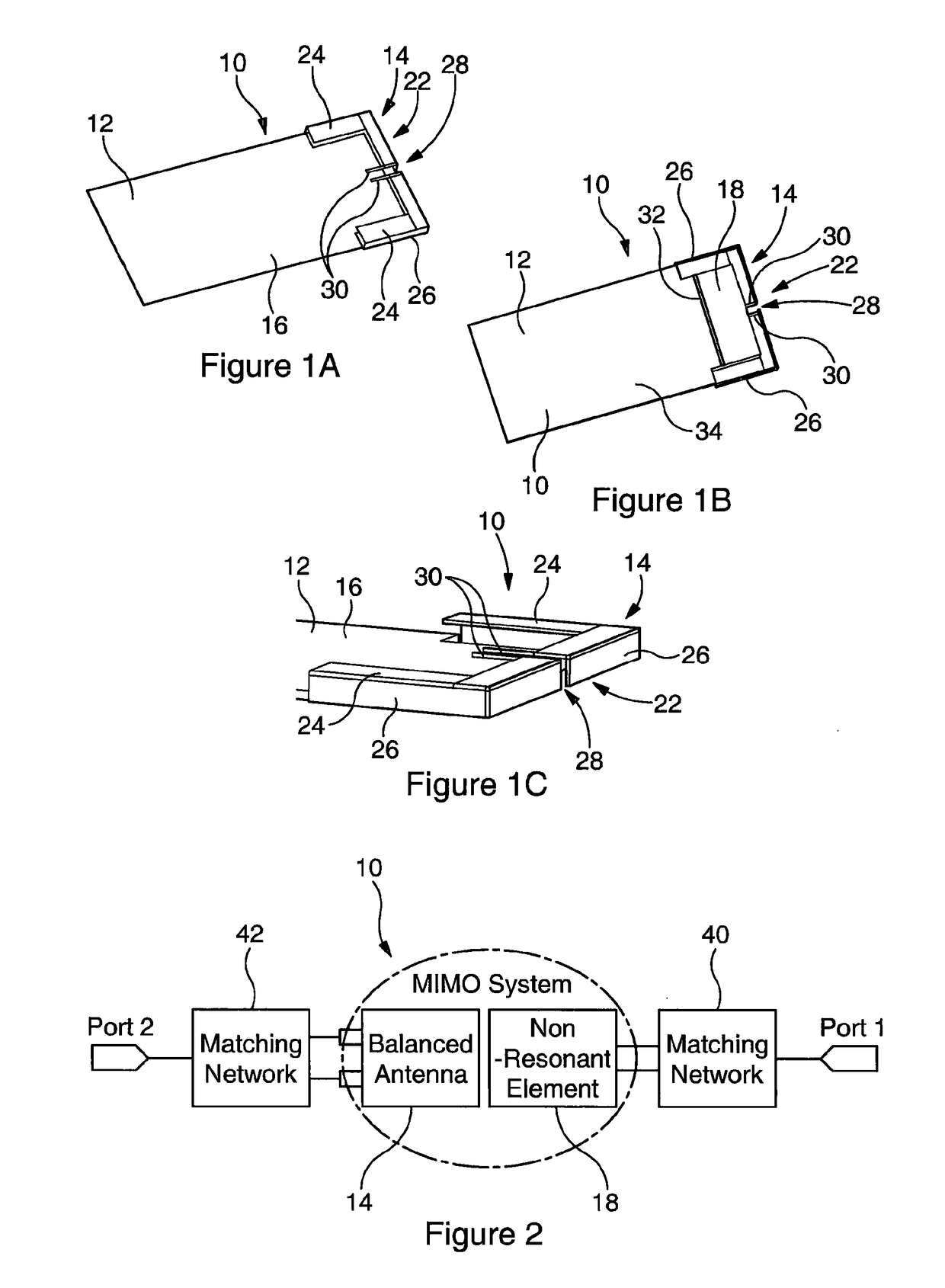
[0057]With reference to FIGS. 1A, 1B and 1C there is shown an antenna 10 according to the present invention, mounted on a PCB 12. The antenna 10 comprises a balanced antenna 14 mounted on a first surface 16 of the PCB 12 and an unbalanced antenna in the form of a non-resonant element 18 mounted on an opposite second surface 20 of the PCB 12. Both the balanced antenna 14 and the non-resonant element 18 are located at the same end 22 of the PCB 12.

[0058]The balanced antenna 14 comprises two inwardly facing planar L-shaped arms 24 which are mounted above and parallel to the plane of the PCB 12. As best illustrated in FIG. 10, each arm 24 is mounted at its outer edge on an orthogonal support 26 which extends from a long edge of the PCB 12, past the end 22 of the PCB 12 and in towards the centre of the end 22. In other words, the balanced antenna 14 is suspended above a U-shaped cut-out around the end 22 of the PCB 12. Notably, the supports 26 and the arms 24 do not meet in the centre of...

second embodiment

[0074]FIG. 8 shows an enlarged underside perspective view of an antenna 50 according to the present invention. The antenna 50 is substantially similar to that shown in FIGS. 1A through 1C except that the structure of the non-resonant element 52 and the balanced antenna 54 is slightly different. More specifically, the non-resonant element 52 is bracket-shaped and comprises an elongate perpendicular end portion 56 mounted along the end 22 of a portion constituting the planar non-resonant element 18. Furthermore, the balanced antenna 54 is “semi-bracket” shaped in that the supports 58 for the L-shaped arms 24 are only provided along the long edge of the PCB 12 and do not extend inwardly towards the centre of the end 22.

third embodiment

[0075]FIG. 9 shows an enlarged underside perspective view of an antenna 60 according to the present invention. The antenna 60 is substantially similar to that shown in FIGS. 1A through 1C except that the non-resonant element 62 is approximately half the width of the non-resonant element 18. Thus, the gap 32 is closer to the end 22 than to the end of the U-shaped cut-out beneath the balanced antenna 14.

[0076]FIG. 10 shows an enlarged top perspective view of an antenna 70 according to a forth embodiment of the present invention. The antenna 70 is substantially similar to that shown in FIGS. 1A through 1C except that the balanced antenna 72 is constituted by a printed dipole having a central substantially T-shaped cut-out 74 separating each arm 75 of the dipole and a small rectangular cut-out 76 at the extreme end of each arm 24, adjacent the long edge of the PCB 12. There is also no cut-out in the PCB 12. It will be noted that the distance between the balanced antenna 72 and the PCB 1...


PUM

PropertyMeasurementUnit
surface areaaaaaaaaaaa
thicknessaaaaaaaaaa
thicknessaaaaaaaaaa

Abstract

The present invention resides in a reconfigurable antenna. The antenna comprises a balanced antenna and an unbalanced antenna mounted on a supporting substrate, with both the balanced antenna and the unbalanced antenna located at the same end of the substrate. The antenna may be configured as a chassis antenna for use in a portable device or configured for Multiple-Input-Multiple-Output (MIMO) applications.

Description

[0001]This application is a national stage entry under 35 U.S.C. § 371 of PCT Application No. PCT / GB2013 / 051855, filed Jul. 12, 2013, which claims the benefit of Great Britain Application No. 1213558.8, filed Jul. 31, 2012. The entire contents of each of PCT Application No. PCT / GB2013 / 051855 and Great Britain Application No. 1213558.8 are incorporated herein by reference in their entirety.FIELD OF THE INVENTION[0002]The invention relates to a reconfigurable antenna. Particularly, but not exclusively, the invention relates to a reconfigurable multiple-input multiple-output (MIMO) antenna for use in a portable electronic device such as a mobile telephone, laptop, personal digital assistant (PDA) or radio.BACKGROUND TO THE INVENTION[0003]Multiple-input multiple-output (MIMO) wireless systems exploiting multiple antennas as both transmitters and receivers have attracted increasing interest due to their potential for increased capacity in rich multipath environments. Such systems can be ...

Claims


Application Information

Patent Timeline
Patent Type & Authority Patents(United States)
IPC IPC(8): H01Q21/00H01Q1/24H01Q9/16H01Q1/52H01Q9/26H01Q21/28G01N33/487
CPCH01Q21/0006G01N33/48721H01Q1/243H01Q21/28H01Q9/16H01Q9/265H01Q1/521
Inventor HU, ZHEN HUAHALL, PETER
Owner SMART ANTENNA TECH
Why Eureka
Try Eureka