3D printing method implemented by movable platform

a 3d printing and movable technology, applied in printing, manufacturing data acquisition/processing, manufacturing tools, etc., can solve the problems of missing nozzles, serious deformation of finished 3d models, and inability to so as to prevent the problem of missing nozzles, reduce the length of pipes behind the nozzles, and stabilize the quality of ink supply functions

Inactive Publication Date: 2019-02-26
XYZPRINTING +1
View PDF16 Cites 5 Cited by
  • Summary
  • Abstract
  • Description
  • Claims
  • Application Information

AI Technical Summary

Benefits of technology

[0008]The disclosure is directed to a 3D printing method implemented by a movable platform, which can prevent traditional 3D printer from having unstably ink supplying and degrading the quality of a finished 3D model when controlling a nozzle to jet inks while it's moving.
[0010]In comparison with related art, the present disclosure uses a movable printing platform to substitute for the nozzle of traditional 3D printers to move along the X axis and the Y axis, so the length of the pipes behind the nozzle can be reduced. Therefore, the unstably ink supplying issue due to the extruded pipes can be easily solved. As a result, it can then stabilize the quality of ink supplying function, and prevent the missing nozzle issues from occurring.
[0011]Besides, the nozzle is restricted to move along the X axis and the Y axis, and the inks are prevented from producing the bubbles due to the movement of the nozzle, so the quality of the finished 3D model is assured. Further, the present disclosure also solve the problem that the traditional nozzle jets inks while it's moving and produces deviations between the positions of the ink jetted on the printing platform and the positions indicated by the 3D file due to the inertia of the moving nozzle.

Problems solved by technology

However, the pipes are easily extruded due to the movement of the nozzle 11, and it may cause unstable pressure of the pumps.
Also, the unstable pressure of the pumps may cause missing nozzle issues.
Therefore, the quality of a finished 3D model will be seriously degraded.
Moreover, the movement of the nozzle 11 will cause the inks inside the ink cartridges or the pipes to produce bubbles, which will affect the quality of the 3D model.

Method used


Image

  • 3D printing method implemented by movable platform
  • 3D printing method implemented by movable platform
  • 3D printing method implemented by movable platform

Examples


first embodiment

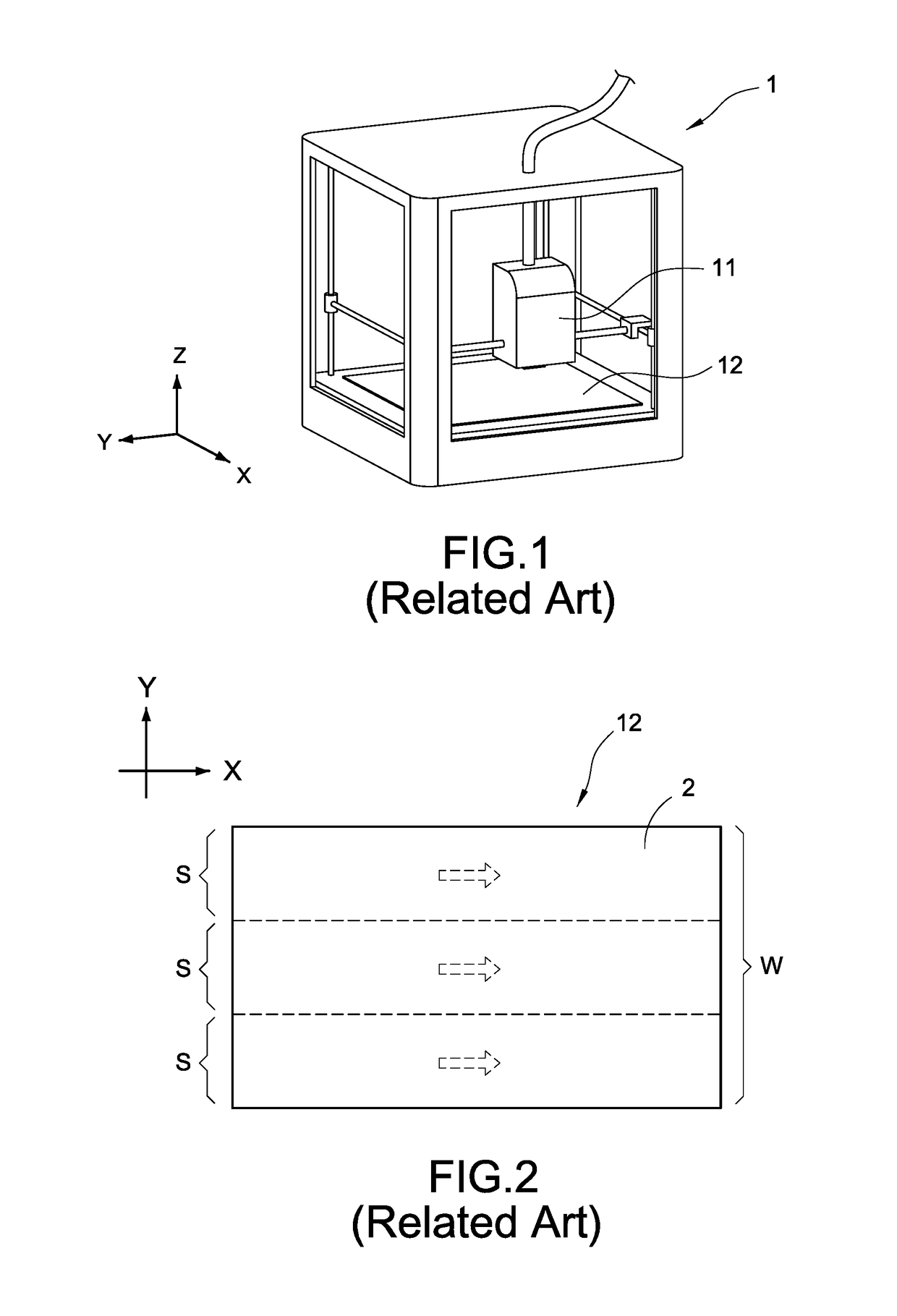
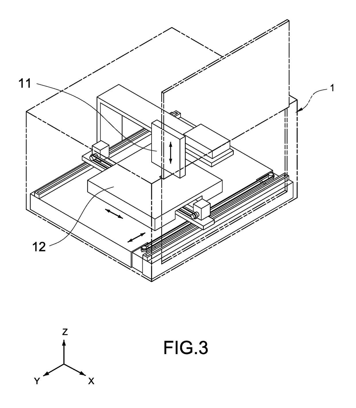
[0025]FIG. 3 is a schematic diagram of a 3D printer of a first embodiment according to the present disclosure. This invention discloses a 3D printing method implemented by a movable platform (refers to as the printing method hereinafter), adopted by a 3D printer 3 shown in FIG. 3, wherein the 3D printer 3 comprises a nozzle 31 and a printing platform 32. In particularly, in this embodiment, the nozzle 31 is restricted to move along an X axis and a Y axis of the 3D printer 3, and the printing platform 32 is movable, which can be controlled by firmware of the 3D printer 3 to move along the X axis and the Y axis.

[0026]The printing platform 32 is arranged to take inks jetted from the nozzle 31, so as to stack the jetted inks to form a physical 3D model upon the printing platform 32. Accordingly, the printing platform 32 needs a big volume. In this embodiment, the 3D printer 3 allows the printing platform 32 to move along the X axis and the Y axis, so the volume of the 3D printer 3 in th...

second embodiment

[0036]FIG. 5 is a printing flowchart of a second embodiment according to the present disclosure. FIG. 5 is used to interpret the printing method of the present disclosure more specifically.

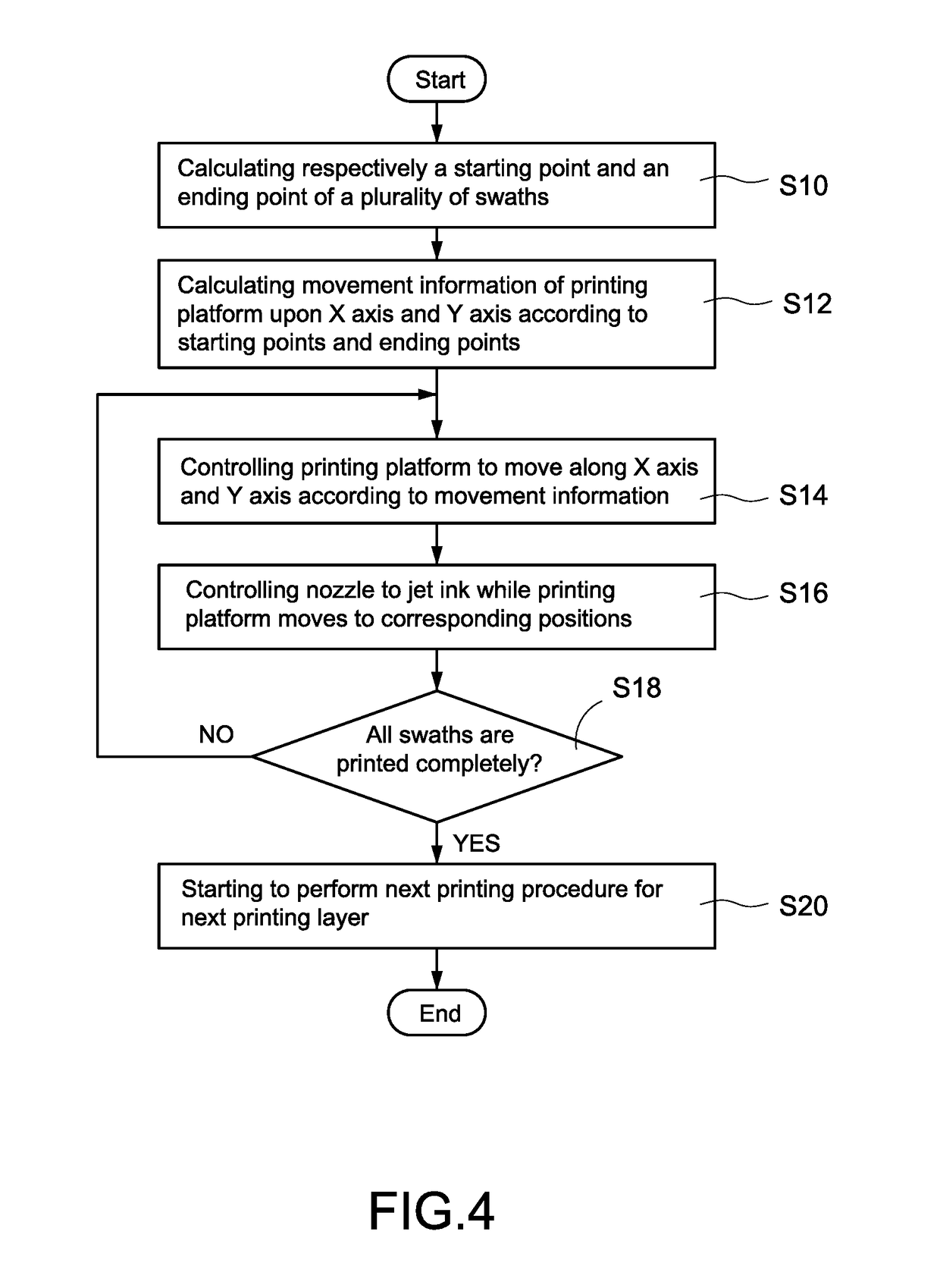
[0037]First, the 3D printer 3 reads an image file of a printing layer (which is a first printing layer) when the 3D printer 3 is about to print a 3D model, so as to obtain information of a plurality of swaths of the printing layer (step S30). Next, the 3D printer 3 calculates respectively, by the firmware, a starting point and an ending point of each swath according to the obtained information (step S32), and calculates movement information of the printing platform 32 upon the X axis and the Y axis according to the starting points and the ending points (step S34).

[0038]Next, the 3D printer 3 controls the printing platform 32 to move along the X axis according to the movement information (step S36), and controls the nozzle 31 to jet ink according to the information obtained at the step S30 while th...


PUM

PropertyMeasurementUnit
lengthaaaaaaaaaa
lengthaaaaaaaaaa
heightaaaaaaaaaa

Abstract

A 3D printing method implemented by movable platform is disclosed. When printing a printing layer, a 3D printer first calculates respectively a starting point and an ending point of each swath of the printing layer, and calculates movement information of a movable printing platform upon an X-axis and a Y-axis of the 3D printer according to the starting points and the ending points. Next, the 3D printer controls the printing platform to move along the X-axis and the Y-axis based on the movement information, and controls a nozzle of the 3D printer to jet ink while the printing platform moves to corresponding positions. Therefore, the 3D printer uses the printing platform to complete printing actions of each swath.

Description

BACKGROUND OF THE INVENTION[0001]1. Technical Field[0002]The technical field relates to a 3D printing method, and specifically to a 3D printing method implemented by a movable platform. 2. Description of Prior Art 3D-JET printer can read user-input 3D file for a physical 3D model and to jet ink through nozzle, so as to stack the jetted ink upon a platform for forming the physical 3D model corresponding to the 3D file, which is very convenient.[0003]FIG. 1 is a schematic diagram of a 3D printing of related art. In particularly, a 3D-JET printer 1 (refers to as the printer 1 hereinafter) comprises a nozzle 11 and a printing platform 12. As shown in FIG. 1, when performing printing actions, the printer 1 typically controls the nozzle 11 to move along an X axis and a Y axis, and also controls the nozzle 11 to jet ink once the nozzle 11 moves to corresponding positions upon the printing platform 12. Therefore, the jetted inks are stacked upon the printing platform 12, so as to form a des...

Claims


Application Information

Patent Timeline
Patent Type & Authority Patents(United States)
IPC IPC(8): B29C67/00B33Y10/00B33Y30/00B33Y50/02B29C64/112B29C64/20B29C64/386
CPCB33Y10/00B29C64/112B33Y30/00B33Y50/02B29C64/20B29C64/386B41J2/01B29C64/393
Inventor LU, TING-YUSU, CHING-HUA
Owner XYZPRINTING
Why Eureka
Try Eureka