Electrical connector

a technology of electrical connectors and connectors, applied in the direction of coupling device connections, switchgear arrangements, coupling device details, etc., can solve the problems of insufficient attraction of resin, inability to ensure liquid tightness, and extended connections of connecting resins, so as to reduce the volume of partition walls and improve liquid tightness

Active Publication Date: 2019-03-05
YAZAKI CORP
View PDF6 Cites 0 Cited by
  • Summary
  • Abstract
  • Description
  • Claims
  • Application Information

AI Technical Summary

Benefits of technology

[0008]An object of the present invention is to solve such a problem, and to provide an electrical connector in which a gap between a partition wall and a bus bar is suppressed to be small, thereby improving liquid tightness, even when resin is thermally shrunk.
[0019]In the electrical connector according to the present invention having the aforementioned configuration, the partition wall is thinned by the thinned part and volume of the partition wall is reduced. In addition, the resin of the partition wall on one side and the resin of the partition wall on the other side partitioned by the metal bus bar are connected by the resin filled in the through hole. Therefore, since the amount of heat shrinkage of both the resin of the partition wall on one side and the resin of the partition wall on the other side partitioned by the bus bar becomes small, the resin filled in the through hole allows the resin of the partition wall on one side and the resin of the partition wall on the other side partitioned by the bus bar to attract each other. Therefore, the gap between the bus bar (metal) and the partition wall (resin) can be suppressed to be small, and the liquid tightness is improved.

Problems solved by technology

However, since the cross-sectional area of the connecting resin is smaller than the amount of heat shrinkage of the resin of the partition wall on one side partitioned by the bus bar and the amount of heat shrinkage of the resin of the partition wall on the other side, there is a possibility that the connecting resin may extend, and the connecting resin cannot sufficiently attract the resin of the partition wall on one side and the resin of the partition wall on the other side partitioned by the bus bar.
For this reason, there is a problem that a gap is formed between the bus bar (metal) and the partition wall (resin), and there is a risk that liquid tightness may not be guaranteed.

Method used


Image

  • Electrical connector
  • Electrical connector
  • Electrical connector

Examples


first embodiment

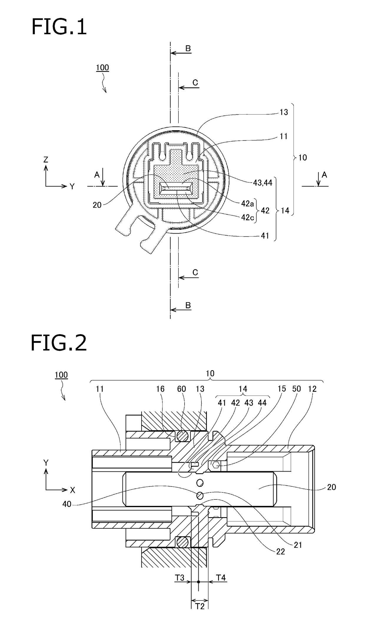
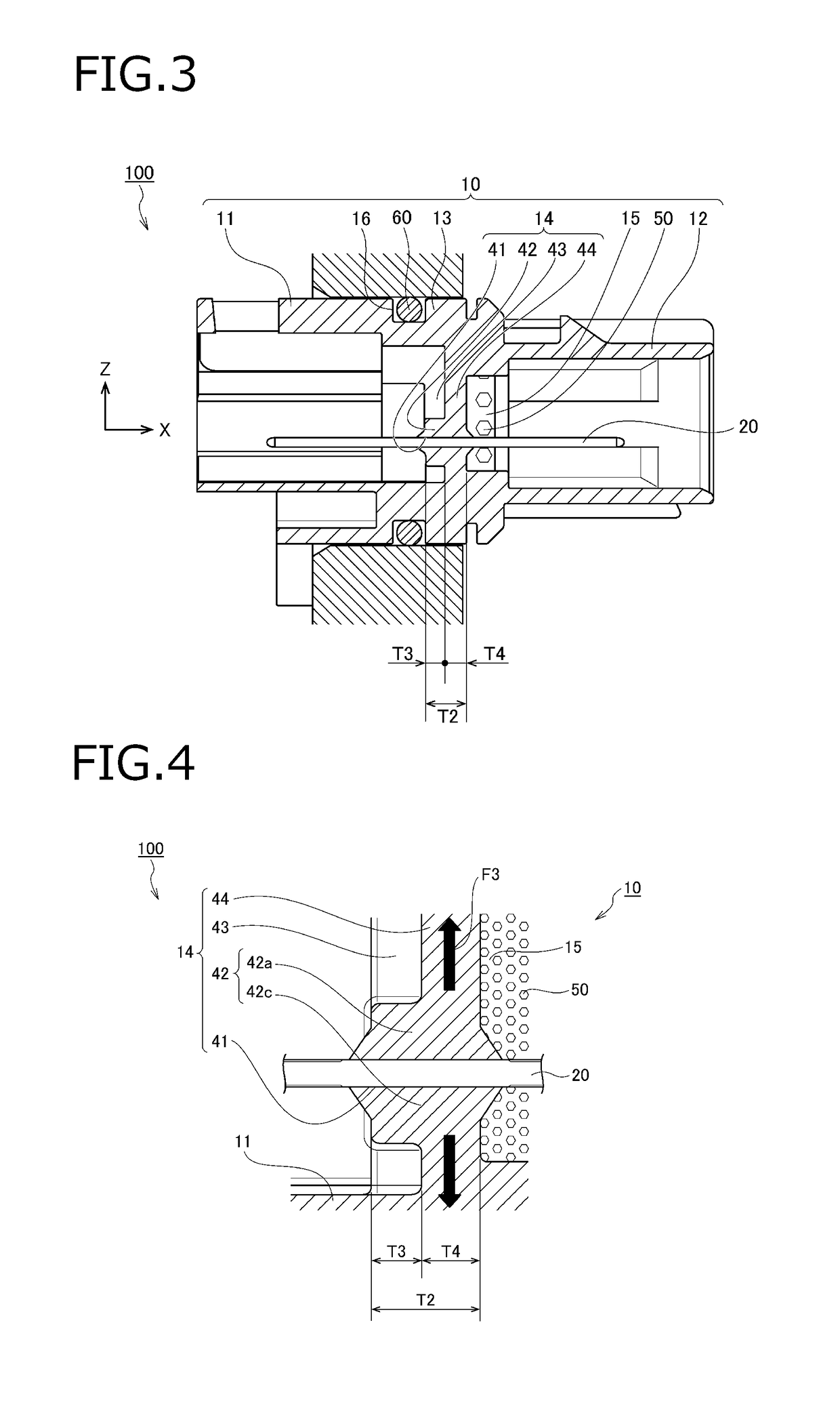
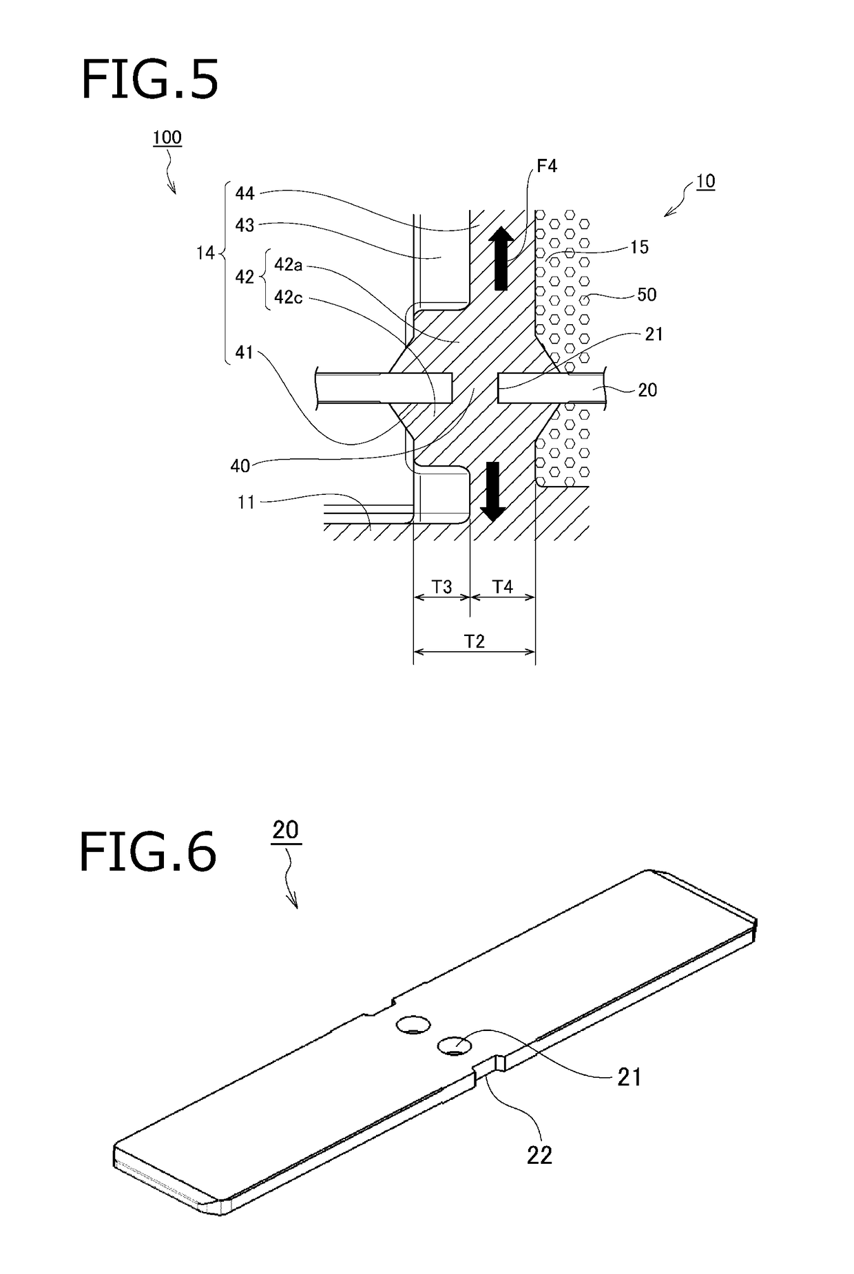
[0030]FIGS. 1 to 6 illustrate an electrical connector according to a first embodiment of the present invention, wherein FIG. 1 is a front view, FIG. 2 is a cross-sectional view illustrating a cross section (taken along line A-A illustrated in FIG. 1) as seen in a plan view, FIG. 3 is a cross-sectional view illustrating a cross-section (taken along line C-C illustrated in FIG. 1) as seen in a side view, FIG. 4 is a cross-sectional view illustrating a part of FIG. 3 in an enlarged manner, FIG. 5 is a cross-sectional view illustrating a cross section (taken along line B-B illustrated in FIG. 1) as seen in a side view in an enlarged manner, and FIG. 6 is a perspective view illustrating a part (bus bar) of the component members.

(Electrical Connector)

[0031]In FIGS. 1 to 6, an electric connector 100 includes a housing 10 made of resin, and a metal bus bar 20 embedded in the housing 10 (the metal bus bar 20 is insert-molded in the housing 10). For the sake of convenience of explanation, a l...

second embodiment

[0044]FIGS. 7 to 9 illustrate an electrical connector according to a second embodiment of the present invention, wherein FIG. 7 is a front view, FIG. 8 is a cross-sectional view illustrating a cross section (taken along line D-D illustrated in FIG. 7) as seen in a side view in an enlarged manner, and FIG. 9 is a cross-sectional view illustrating a cross section (taken along line E-E illustrated in FIG. 7) as seen in a side view in an enlarged manner. The same or corresponding parts as those in the first embodiment are denoted by the same reference numerals, and a partial explanation will be omitted.

(Rib)

[0045]In FIGS. 7 to 9, an electrical connector 200 includes a bus bar 20 and a housing 30. The housing 30 corresponds to a housing in which a rib 45 integrated with the thinning residue portion 44 is provided in the thinning removal portion 43 of the housing 10 in the electrical connector 100.

[0046]The rib 45 connects the outer periphery of the hole periphery portion 42 and the inner...

modification example

[0054]In the above description, the phases (positions in the X-Y direction) of the upper rib 45a, the lower rib 45c, and the through hole 21 coincide with each other. However, the present invention is not limited thereto, and the respective phases may be different from each other. At this time, although the heat shrinkage force of the upper rib 45a and the heat shrinkage force of the lower rib 45c are not transmitted in a substantially linear manner via the connecting resin 40, but are transmitted in an oblique direction via the connecting resin 40. Therefore, it is possible to obtain the operational effect (the operational effect of decreasing the force to pull apart the hole peripheral upper portion 42a and the hole peripheral lower portion 42c) according to the above configuration.

[0055]In the above description, the number of bus bar 20 is one, but the present invention is not limited thereto, and a plurality of bus bars 20 may be used. In this case, a plurality of bus bars 20 ma...


PUM


Abstract

An electrical connector includes a tubular housing having a partition wall extending in a direction perpendicular to a longitudinal direction of the tubular housing and a bus bar embedded in the partition wall of the housing in a state of penetrating the partition wall in the longitudinal direction. The partition wall is located at a substantially center in the longitudinal direction. A through hole is formed at a position of the bus bar at which the bus bar is embedded in the partition wall. A part of the partition wall is filled in the through hole. A range of the partition wall away from the position at which the bus bar is embedded in the partition wall has a thinned part.

Description

CROSS REFERENCE TO RELATED APPLICATIONS[0001]This application is based on Japanese Patent Application (No. 2017-044611) filed on Mar. 9, 2017, the contents of which are incorporated herein by reference.BACKGROUND OF THE INVENTION1. Field of the Invention[0002]The present invention relates to an electrical connector, in particular, to an electrical connector which is installed on a wall surface of a container in which liquid or gas is enclosed, thereby enabling current to flow between an electric device inside the container and an electrical device outside the container.2. Description of the Related Art[0003]In the related art, for example, on the wall surface of a main body (hereinafter referred to as a “container”) constituting a transmission of an automobile, an electrical connector is installed which enabling current to flow between electric devices installed inside and outside the container.[0004]The electrical connector includes a tubular resin housing having a partition wall a...

Claims


Application Information

Patent Timeline
Patent Type & Authority Patents(United States)
IPC IPC(8): H01R13/52H02G3/22H01R13/405H02G15/013H01R31/06H01R13/73
CPCH01R13/5202H01R13/405H01R13/521H01R13/5216H02G3/22H02G15/013H01R31/06H01R2201/26H01R13/73H01R13/46H02B13/005
Inventor NAGAYAMA, MASATAKASAKAMOTO, NOBUYUKITAKAHASHI, KENJI
Owner YAZAKI CORP
Why Eureka
Try Eureka