
Mandrel-pulling distance sensing assembly of an electric rivet gun

a technology of mandrel and mandrel, which is applied in the field of mandrel pulling distance sensing assembly of an electric rivet gun, can solve the problems of inability to accurately control the linear low accuracy of positioning the snapping device at specific positions, and inability to accurately control the distance between the mandrel and the snapping devi

Active Publication Date: 2019-03-19
LIN YU TANG
View PDF2 Cites 6 Cited by
  • Summary
  • Abstract
  • Description
  • Claims
  • Application Information

AI Technical Summary

Benefits of technology

The patent describes a device that uses a sensor to detect the movement of a seat in a machine. This sensor uses a Hall effect to measure changes in magnetic field and send signals to a control unit, which then operates a motor to move the seat to a specific position. This ensures accurate positioning and control of the movement of a snapping device.

Problems solved by technology

However, rotational speeds of the rotating shaft of the motor differ with regard to input voltages and the different rotational speeds directly influence a time difference which is occurred when the rotating shaft is switched to rotate reversely.
Moreover, after long-term use of the gear set and the motor, teeth of the gear set may be worn down or impurities may accumulate between the teeth of the gear set, causing inaccuracy of positioning the snapping device at specific positions by setting the number of rotation of the rotating shaft of the motor.
Therefore, no matter positions of the snapping device is controlled by the number of rotations of the rotating shaft of the motor or by the photo interrupters, the accuracy of positioning the snapping device at specific positions is low.
The linear distance that the snapping device and the mandrel are pulled cannot be accurately controlled.

Method used


Image

  • Mandrel-pulling distance sensing assembly of an electric rivet gun
  • Mandrel-pulling distance sensing assembly of an electric rivet gun
  • Mandrel-pulling distance sensing assembly of an electric rivet gun

Examples


Embodiment Construction

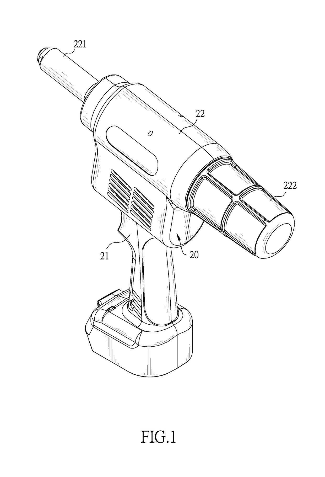
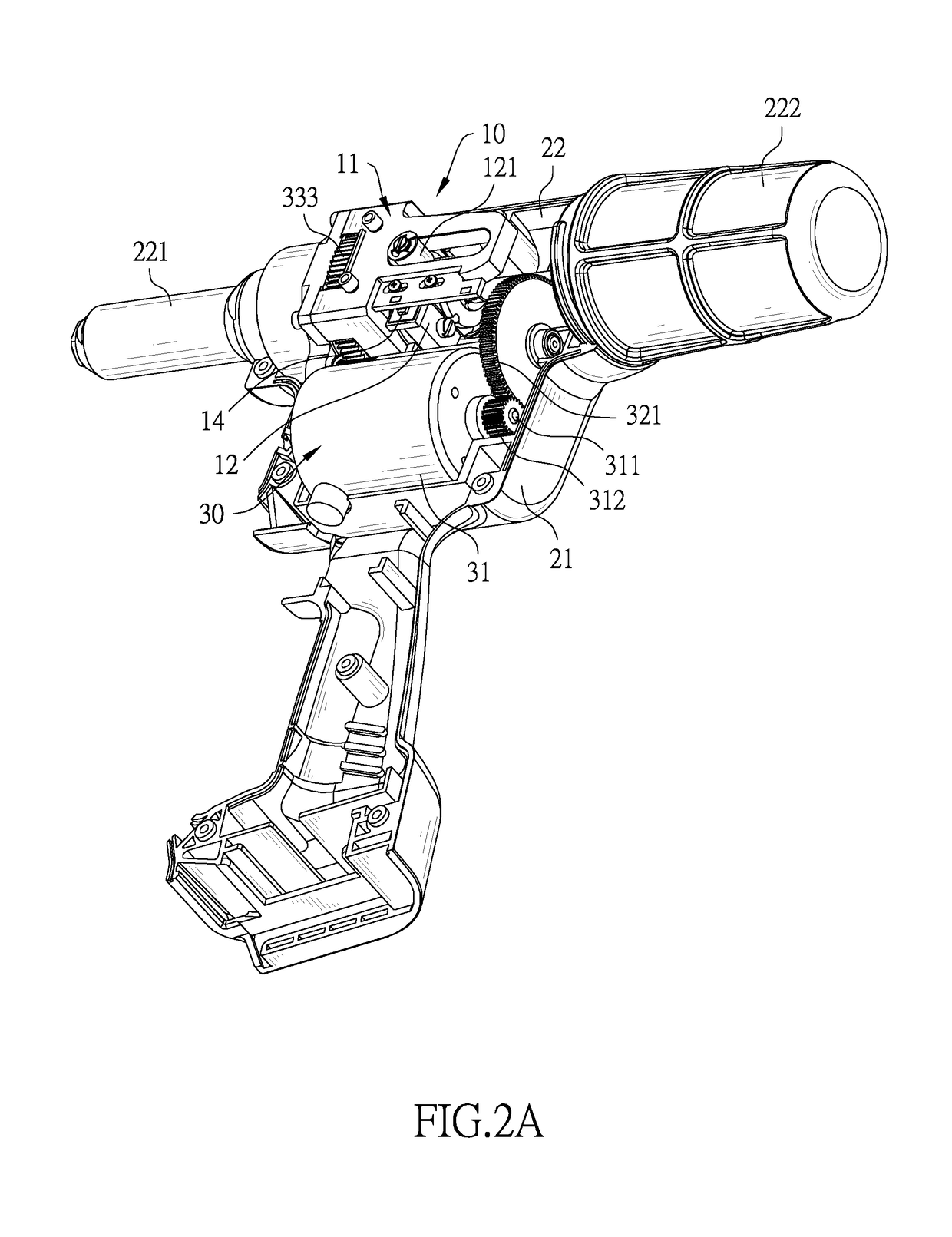
[0023]With reference to FIGS. 1 and 2A, a mandrel-pulling distance sensing assembly 10 in accordance with the present invention is mounted in a housing 20 of an electric rivet gun. The housing 20 has a handle 21 and a barrel 22. The barrel 22 is formed on an upper end of the handle 21 and has two opposite ends. The two opposite ends of the barrel 22 are respectively defined as a front end 221 and a rear end 222. A snapping device for snapping a mandrel of a rivet is mounted in the front end 221 of the barrel 22.

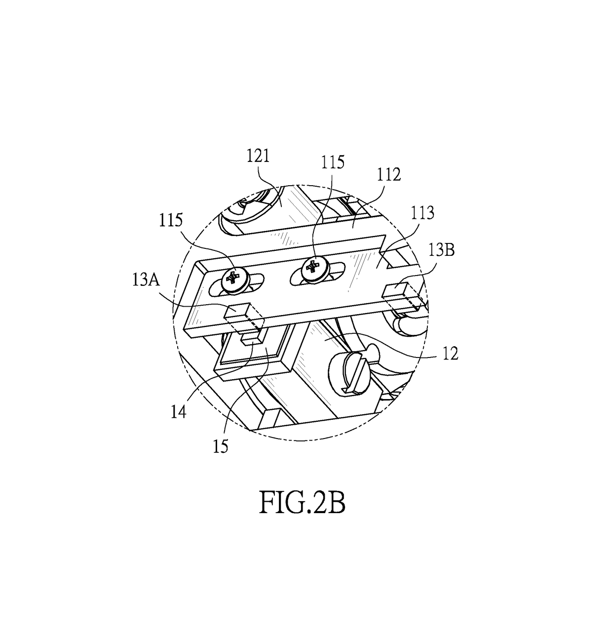
[0024]With further reference to FIGS. 2B, 3, and 4, the mandrel-pulling distance sensing assembly 10 is mounted in the barrel 22 of the housing 20 and comprises a stationary seat 11, a moving seat 12, two magnetic elements 13A, 13B, and a Hall effect sensor 14.

[0025]The stationary seat 11 is securely fixed in the barrel 22 of the housing 20 and has a base 111, two extension arms 112, and a mounting panel 113. The base 111 is securely mounted in the housing 20. The extension a...


PUM

PropertyMeasurementUnit
Widthaaaaaaaaaa
Distanceaaaaaaaaaa

Abstract

A mandrel-pulling distance sensing assembly of an electric rivet gun is mounted in a barrel of a housing and has a stationary seat, a moving seat, two magnetic elements separately fixed on the stationary seat, and a Hall effect sensor fixed on the moving seat. The moving seat is driven by a driving assembly of the electric rivet gun and is movable relative to the stationary seat. While the Hall effect sensor moves along with the moving seat between the two magnetic elements, the Hall effect sensor detects a changing magnetic field and produces and outputs a changing voltages to a control unit to allow the control unit to operate the driving assembly according to the changing voltages. Thus, the moving seat can be accurately positioned and moving ranges of a snapping device that is driven by the driving assembly can be accurately controlled.

Description

CROSS-REFERENCE TO RELATED APPLICATIONS[0001]This application is based upon and claims priority under 35 U.S.C. 119 from Taiwan Patent Application No. 107200453 filed on Jan. 10, 2018 and Taiwan Patent Application No. 107203789 filed on Mar. 23, 2018, which are hereby specifically incorporated herein by this reference thereto.BACKGROUND OF THE INVENTION[0002]1. Field of the Invention[0003]The present invention relates to a rivet gun, especially to a mandrel-pulling distance sensing assembly of an electric rivet gun.[0004]2. Description of the Prior Art(s)[0005]A rivet is a kind of fastener that can hold at least two working pieces together and includes a mandrel and a rivet body mounted on an end of the mandrel. A rivet gun holds and pulls the mandrel, causing the rivet body to deform and hold the working pieces between a flange of the rivet body and a deformed portion of the rivet body.[0006]A conventional electric rivet gun has a motor and a snapping device that is used for snappi...

Claims


Application Information

Patent Timeline
IPC IPC(8): B21J15/28B21J15/04B21J15/26B23P17/00G01R33/07
CPCB21J15/043B21J15/28B21J15/26G01R33/072
Inventor LIN, YU-TANGKAO, HSIEN-YU
Owner LIN YU TANG
Learn More