Additive machine utilizing rotational build surface

a technology of additive manufacturing and build surface, which is applied in the direction of additive manufacturing process, manufacturing tools, turbines, etc., can solve the problems of large capacity machines and workspaces, complex structures radiating away, and the manufacture of such parts via conventional methods and known additive manufacturing methods is difficul

Active Publication Date: 2019-03-26
GENERAL ELECTRIC CO
View PDF34 Cites 1 Cited by
  • Summary
  • Abstract
  • Description
  • Claims
  • Application Information

AI Technical Summary

Benefits of technology

[0039]The present invention has advantages over the prior art. The radial additive manufacturing process described above is far more flexible as to shape and configuration of axi-symmetric parts. In addition, it is believed that the radial additive manufacturing process provides the ability to make parts that have more complex geometries that would be not possible with conventional manufacturing methods. Such more complex parts include dual material axi-symmetric parts and integrally bladed rotors. In addition, manufacture of such parts requires fewer support structures and the parts can be larger than conventional methods of forming such parts. The apparatus and method described above allow for the flushing of powder using a combination of gravity and spindle rotation. Also, it is believed that the radial manufacturing process described above requires less space and smaller equipment for a given part as compared to conventional manufacturing methods.

Problems solved by technology

Such parts generally have a radial symmetry but often have very complex structures radiating away from the axis.
As a result, manufacture of such parts via conventional methods and known additive manufacturing methods can be difficult and require large capacity machines and workspaces.

Method used


Image

  • Additive machine utilizing rotational build surface
  • Additive machine utilizing rotational build surface
  • Additive machine utilizing rotational build surface

Examples


Embodiment Construction

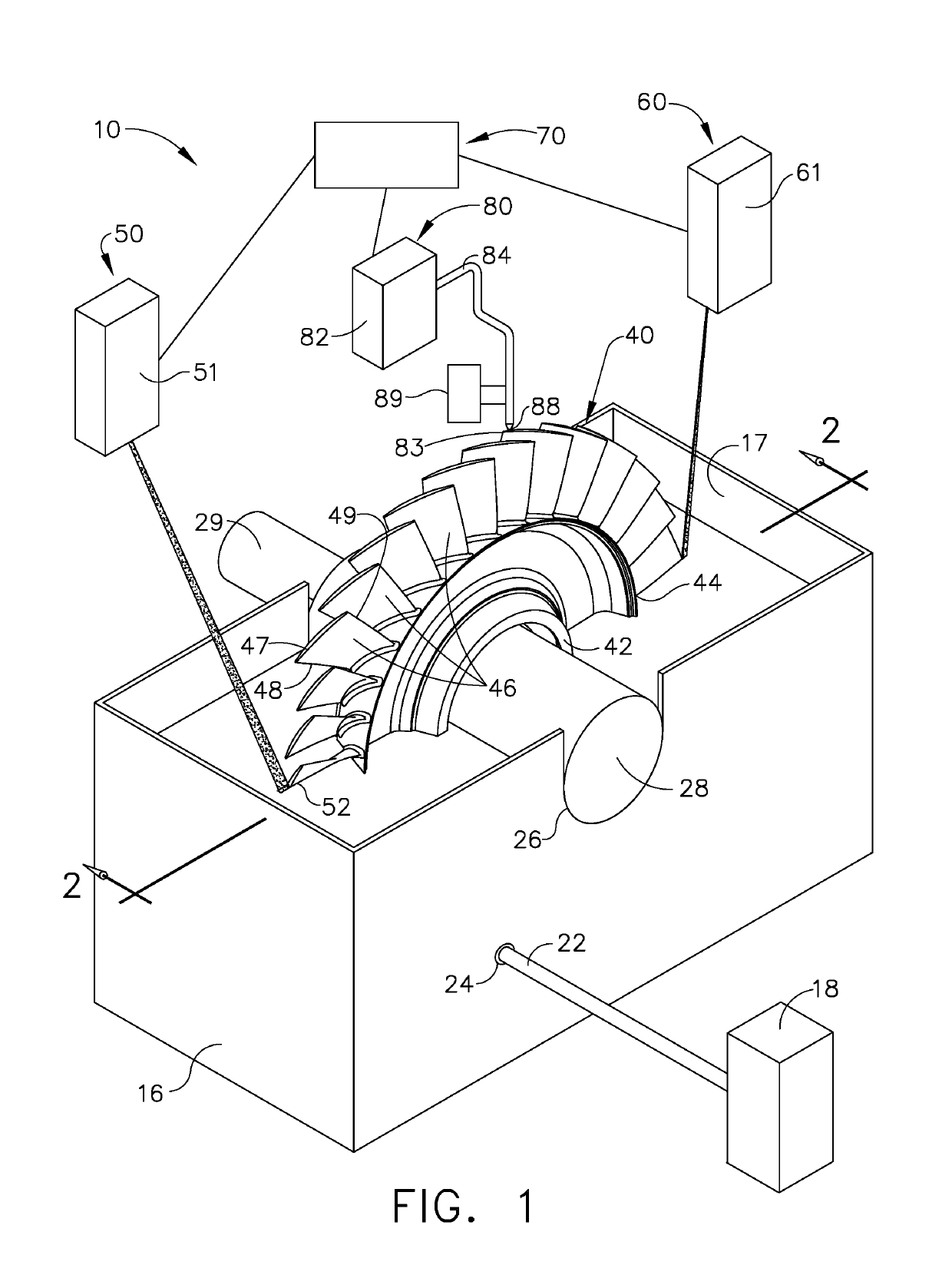
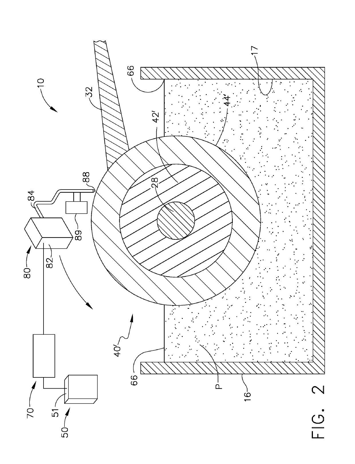
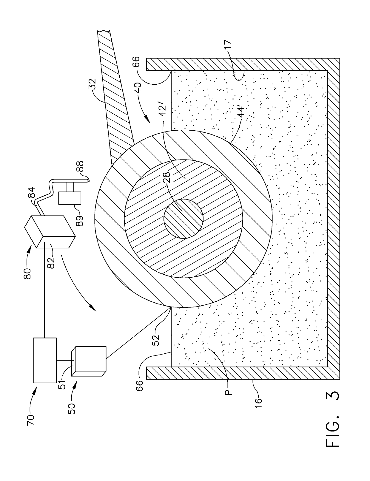
[0013]Referring to the drawings wherein identical reference numerals denote the same elements throughout the various views, FIG. 1 shows an apparatus 10 for radially building axially symmetric parts. As illustrated, apparatus 10 includes a powder-pond additive manufacturing system 50 and a powder-fed manufacturing system 80. The two systems are configured to be used separately, one after the other, or substantially simultaneously to build up an axially symmetric part as will be discussed further below. By way of example and not limitation, such axially symmetric parts that can be built using the apparatus 10 include the following: compressor fans, turbine fans, pump impellers, and the like.

[0014]Continuing to refer to FIG. 1, the powder-pond additive manufacturing system 50 of apparatus 10 includes a box 16 that defines a reservoir 17 for containing a powder P. It should be appreciated that the box 16 is a container, vat, or other vessel. The box 16 is fluidly connected to a source ...


PUM

PropertyMeasurementUnit
thicknessaaaaaaaaaa
energyaaaaaaaaaa
distanceaaaaaaaaaa

Abstract

An apparatus for manufacturing an axi-symmetric part. The apparatus includes a vessel configured to contain the powder. The vessel is also configured to receive a part such that at least a portion of the part contacts the powder contained within the vessel. A first energy source is configured to generate a first beam of energy. The first beam of energy is configured to melt the powder at a first predetermined location such that the melted powder fuses to the part.

Description

BACKGROUND OF THE INVENTION[0001]The present invention relates to additive manufacturing of a 3-D object and more specifically to additive manufacturing of an object on a rotatable surface.[0002]Complex mechanical parts used in the aircraft, power, and other industries are often configured to rotate or to surround a rotating object. Such parts generally have a radial symmetry but often have very complex structures radiating away from the axis. As a result, manufacture of such parts via conventional methods and known additive manufacturing methods can be difficult and require large capacity machines and workspaces. Also, buildup of larger single part and / or multipart axi-symmetric assemblies conventionally requires separate build steps. Therefore there is a need for an apparatus and method for building an axi-symmetric part without separate build steps.BRIEF DESCRIPTION OF THE INVENTION[0003]This need is addressed by an apparatus configured to rotate a part such that different surfac...

Claims


Application Information

Patent Timeline
Patent Type & Authority Patents(United States)
IPC IPC(8): B23K26/342B29C64/205B29C64/241B29C64/282B29C64/153B22F5/04B22F5/00B22F3/105B23K26/08B23K26/06B33Y10/00B33Y30/00B23K101/00
CPCB23K26/342B22F5/009B22F5/04B23K26/0604B23K26/0823B29C64/153B29C64/205B29C64/241B29C64/282B22F3/1055Y02P10/295B22F2003/1056B23K2101/001B33Y10/00B33Y30/00Y02P10/25B22F12/226B22F10/37B22F10/25B22F12/70B22F12/53B22F10/68B22F12/45
Inventor MCCARREN, JOHN MICHAELROBERTS, HERBERT CHIDSEYESTILL, ERIC ALANFLYNN, PETER ANDREW
Owner GENERAL ELECTRIC CO
Why Eureka
Try Eureka