Defining routing domain for distributed packet processing

a technology for routing domains and packet processing, applied in data switching networks, digital transmission, electrical appliances, etc., can solve the problems of ccp resources being burdened by large amount of data to send in addition to other control messages, and achieve the effect of facilitating packet processing and reducing memory and traffic load

Active Publication Date: 2019-03-26
NICIRA
View PDF5 Cites 33 Cited by
  • Summary
  • Abstract
  • Description
  • Claims
  • Application Information

AI Technical Summary

Benefits of technology

[0004]For a managed network including multiple host machines implementing multiple logical networks, some embodiments provide a method that reduces the memory and traffic load required to implement the multiple logical networks. The method does this by using the concept of a routing domain. A routing domain as used in this disclosure refers to a set of logical forwarding elements (LFEs) (e.g., logical switches and logical routers) that are implemented on each host machine to perform first-hop logical forwarding, examples of routing domains will be provided in FIGS. 2A-D. The method generates configuration data for each of multiple host machines. The configuration data includes (i) data to configure a host machine to implement a set of LFEs that belong to a set of routing domains and (ii) identifiers for each routing domain in the set of routing domains. The method then receives data regarding tunnel endpoints (e.g., virtual extensible local area network (VXLAN) tunnel endpoints (VTEPs)) operating on each of the host machines and an association with the routing identifiers sent to the host machines. The method then generates a routing domain VTEP list for each routing domain based on the data received from each of the host machines. The routing domain VTEP list for a particular routing domain includes a list of the VTEPs associated with the routing domain. In some embodiments, the VTEP list includes addresses for the VTEPs (e.g., IP addresses). The method then sends each routing domain VTEP list to the host machines implementing an LFE for the routing domain. The host machines can then use the routing domain VTEP list to facilitate packet processing (e.g., address resolution protocol (ARP) packets, gratuitous ARP (GARP) packets, etc.).

Problems solved by technology

Such a large amount of data to send in addition to other control messages is a significant burden on the CCP resources.

Method used


Image

  • Defining routing domain for distributed packet processing
  • Defining routing domain for distributed packet processing
  • Defining routing domain for distributed packet processing

Examples


Embodiment Construction

[0018]In the following description, numerous details are set forth for the purpose of explanation. However, one of ordinary skill in the art will realize that the invention may be practiced without the use of these specific details. In other instances, well-known structures and devices are shown in block diagram form in order not to obscure the description of the invention with unnecessary detail.

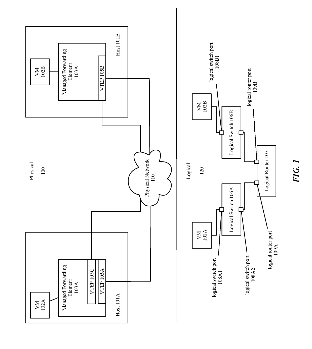
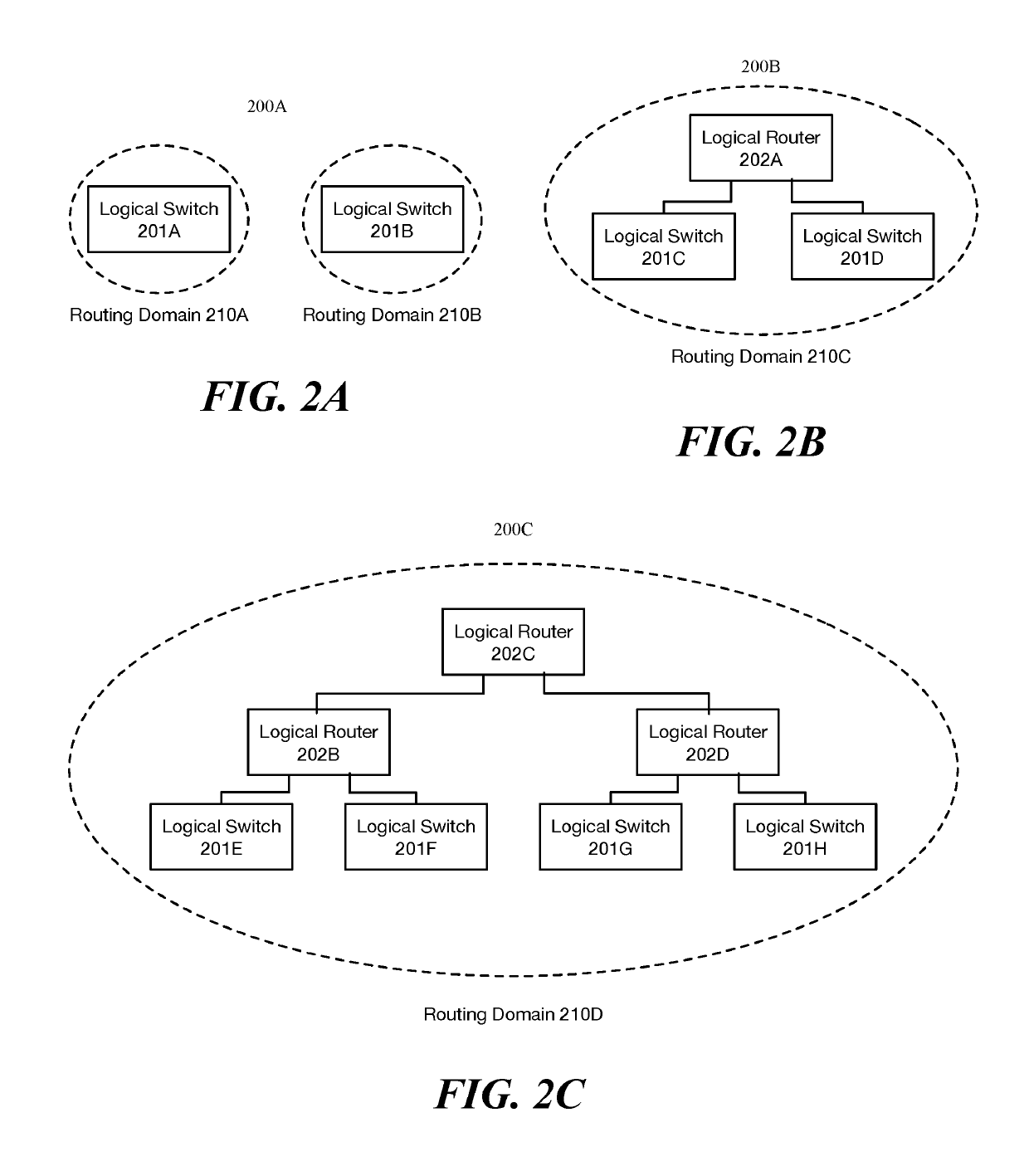
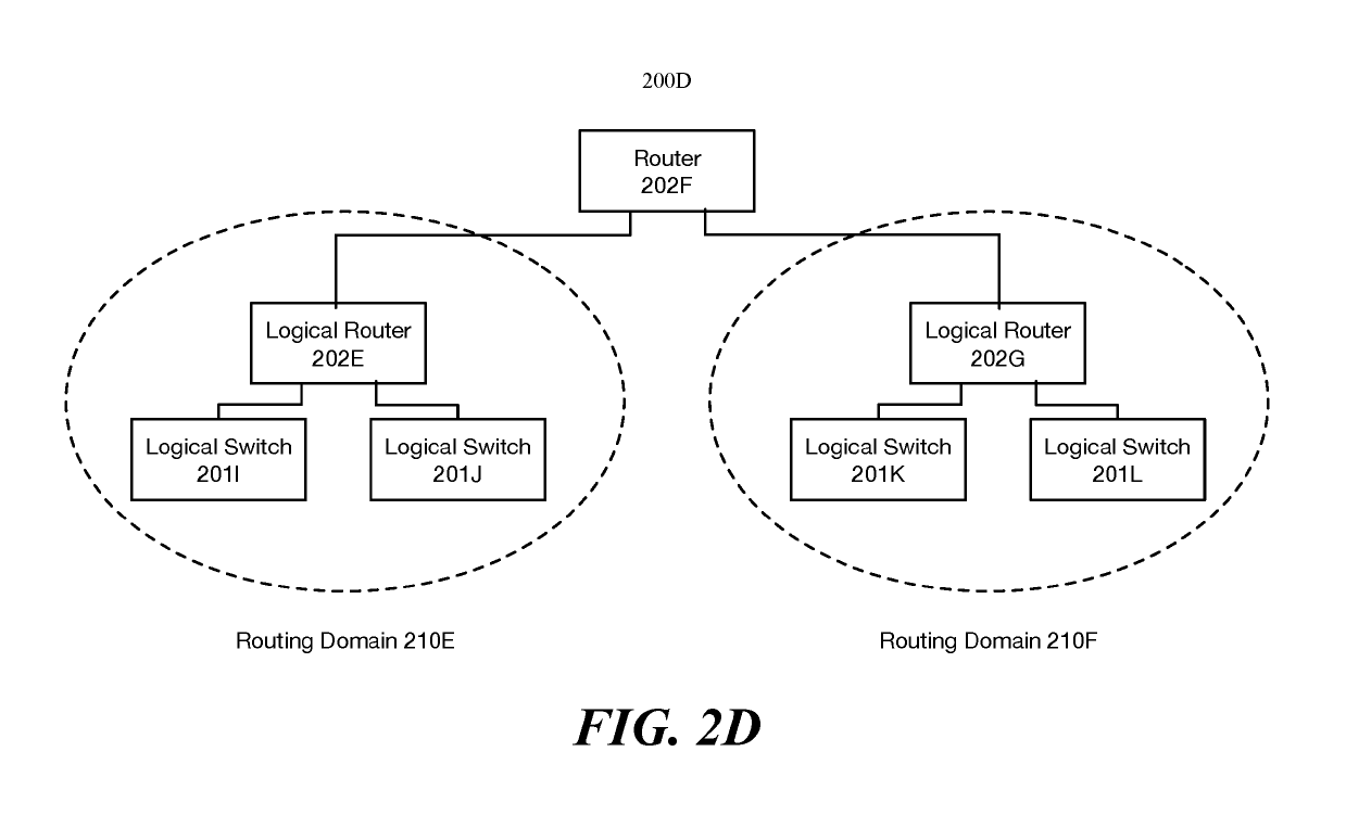
[0019]For a managed network including multiple host machines implementing multiple logical networks, some embodiments provide a method that reduces the memory and traffic load required to implement the multiple logical networks. The method does this by using the concept of a routing domain. A routing domain as used in this disclosure refers to a set of logical forwarding elements (LFEs) (e.g., logical switches and logical routers) that are implemented on each host machine to perform first-hop logical forwarding, examples of routing domains will be provided in FIGS. 2A-D. In some embodiments...


PUM


Abstract

For a managed network including multiple host machines implementing multiple logical networks, some embodiments provide a method that reduces the memory and traffic load required to implement the multiple logical networks. The method generates configuration data for each of multiple host machines including (i) data to configure a host machine to implement a set of logical forwarding elements that belong to a set of routing domains and (ii) identifiers for each routing domain in the set of routing domains. The method then receives data regarding tunnels endpoints operating on each of the host machines and an association with the routing identifiers sent to the host machines. The method then generates a routing domain tunnel endpoint list for each routing domain based on the data received from each of the host machines including a list of the tunnel endpoints associated with the routing domain which the host machines can use to facilitate packet processing.

Description

BACKGROUND[0001]In current systems, all logical switches connected to a distributed logical router (DLR) (e.g., a tenant logical router (TLR) or provider logical router (PLR)) must be configured on each host machine implementing the distributed logical router. Each machine implementing the distributed logical router reports a tunnel endpoint (e.g., a virtual extensible local area network (VXLAN) tunnel endpoint (VTEP)) to a central control plane (CCP) (e.g., a controller or set of controllers). For a current ARP implementation, each host machine is required to report a <logical switch, VTEP> association (or mapping) for all logical switches connected to the distributed logical router even if the host machine is not hosting any compute nodes connected to a particular logical switch.[0002]In a large-scale virtualized environment, there may be hundreds or even thousands of host machines implementing a same distributed logical router. If the DLR connects to 1000 logical switches, ...

Claims


Application Information

Patent Timeline
Patent Type & Authority Patents(United States)
IPC IPC(8): H04L12/721H04L12/46H04L12/733H04L45/122
CPCH04L45/44H04L45/122H04L12/4641H04L12/4633H04L45/04
Inventor JIANG, CAIXIASHEN, JIANJUNTHAKKAR, PANKAJCHANDA, ANUPAMZHANG, RONGHUACHANDRASHEKHAR, GANESANLIU, VICKYWAN, DAPAN, FRANKWANG, HUAHAN, DONGHAI
Owner NICIRA
Why Eureka
Try Eureka