Directional pixel for multiple view display

a directional pixel and display technology, applied in the field of directional pixel design, can solve the problems of limited depth of field and limited angular resolution of display, and achieve the effect of improving directional pixel design and high angular resolution

Active Publication Date: 2019-03-26
AVALON HOLOGRAPHICS INC
View PDF63 Cites 3 Cited by
  • Summary
  • Abstract
  • Description
  • Claims
  • Application Information

AI Technical Summary

Benefits of technology

[0010]It is an object of the present disclosure to improve directional pixel design for the creation of a high angular resolution, wide field of view, multiple view display.
[0012]Instances of directional pixels previously known in the art provide a limited number of distinct light emission directions, creating displays with limited angular resolution and limited depth of field. It is an object of the present disclosure to provide an increased number of distinct light emission directions, creating high angular resolution displays with improved depth of field.
[0013]It is an object of the present disclosure to collimate, manipulate, or tune light beams for small scale pixel sizes within an optical microcavity before the light beams propagate through the system; this reduces the spectral bandwidth of the output light beams, maximizing control of the output angle.
[0014]It is an object of the invention to provide small scale (nano- or micro-scale) pixels. When used in a display, the reduced pixel size allows the system to output a greater number of light beams in a greater number of distinct directions; this improves upon pixels previously known in the art by allowing the generation of higher angular resolution displays with improved effective resolution of multi-dimensional objects. The increased number of light-field display views allows a viewer located at any viewing position to simultaneously receive multiple views; this is known as a super multi-view (SMV) display. An SMV display, providing improved angular resolution, eliminates the accommodation-convergence conflict and produces displays with a higher quality depth of field.

Problems solved by technology

Instances of directional pixels previously known in the art provide a limited number of distinct light emission directions, creating displays with limited angular resolution and limited depth of field.

Method used


Image

  • Directional pixel for multiple view display
  • Directional pixel for multiple view display
  • Directional pixel for multiple view display

Examples


Embodiment Construction

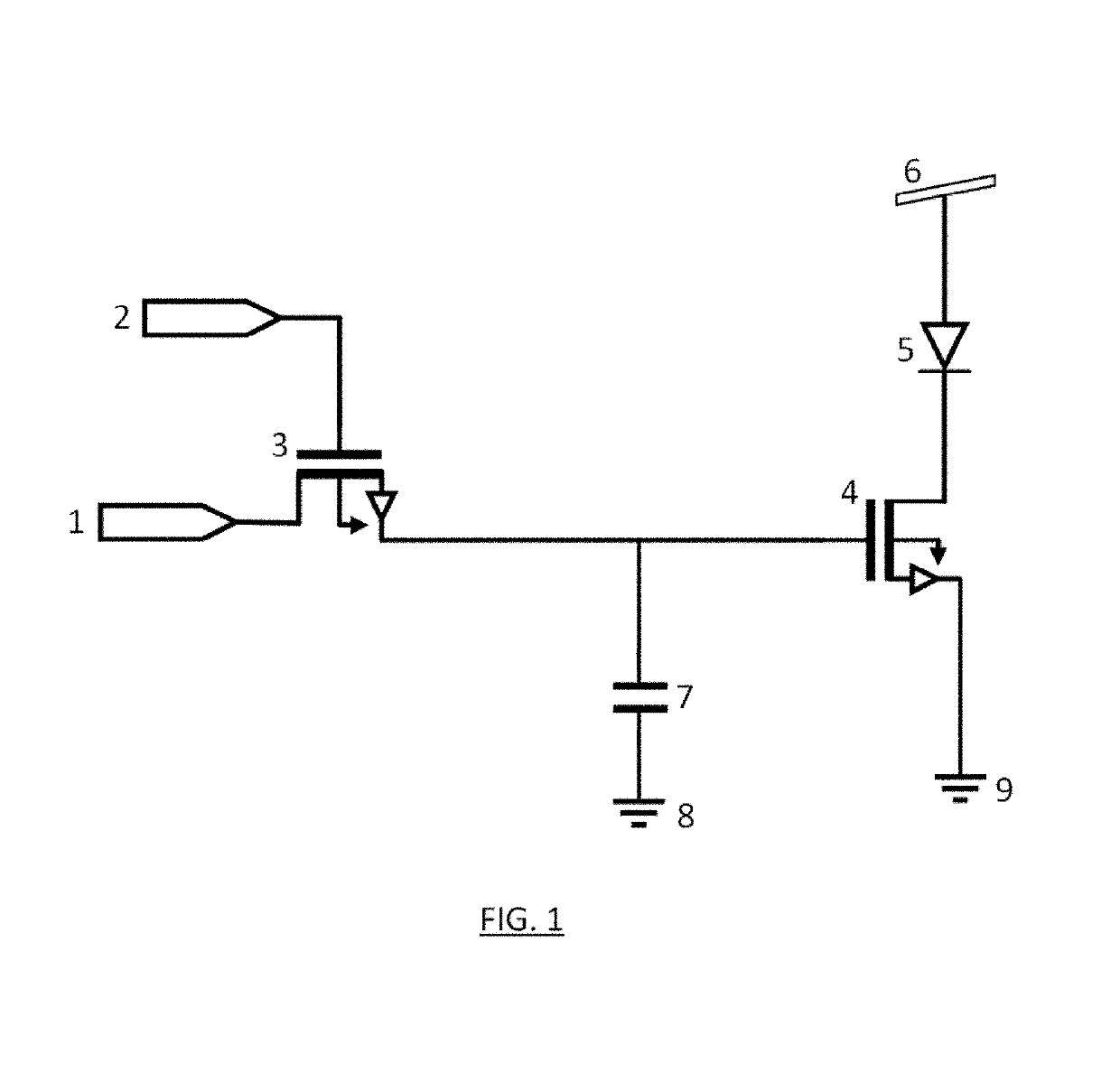
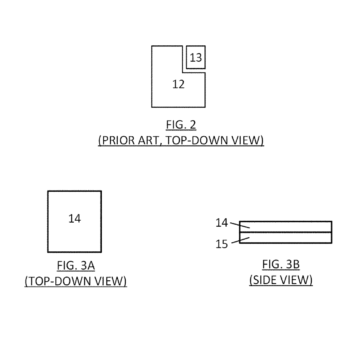
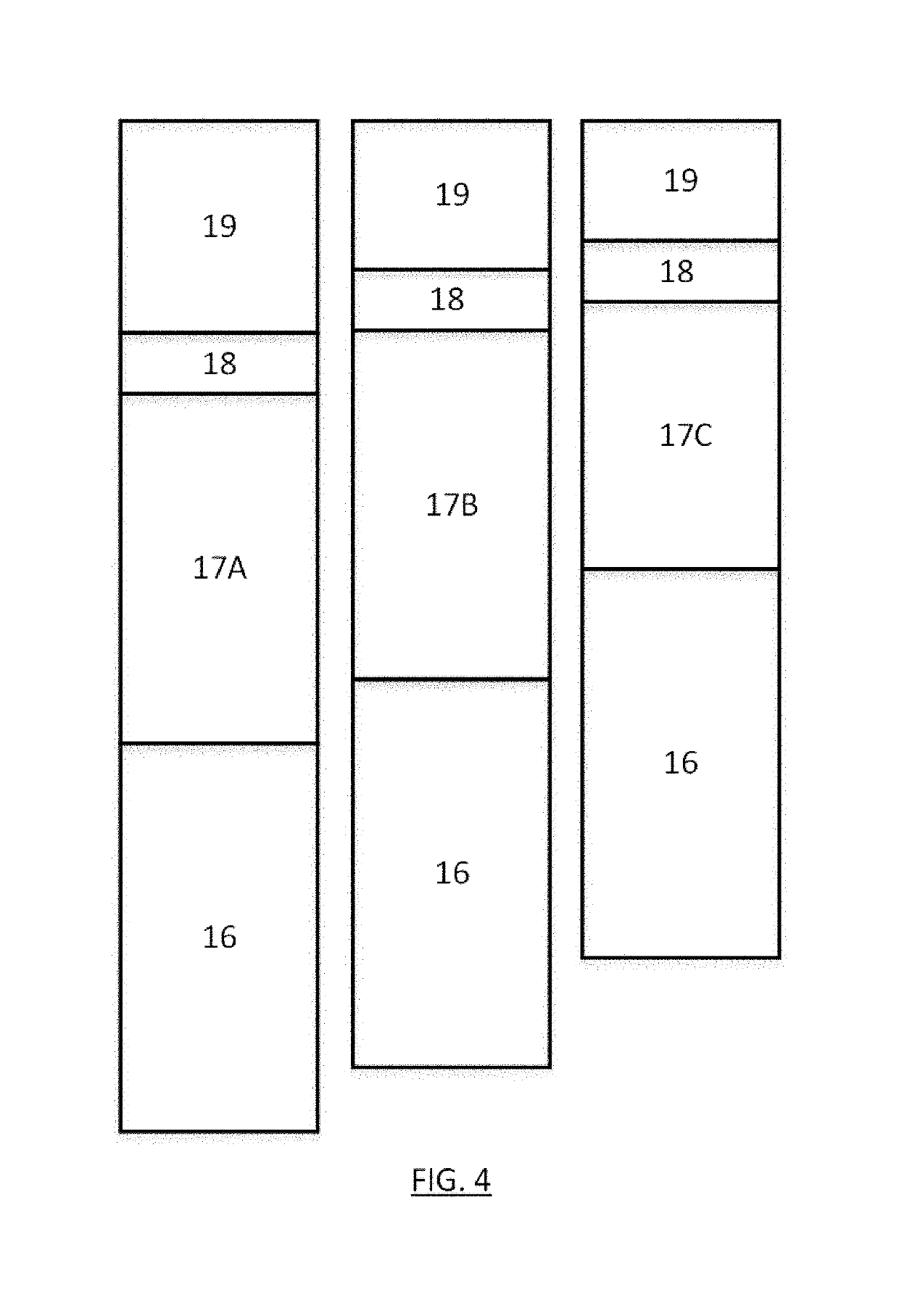
[0028]Various features of the invention will become apparent from the following detailed description taken together with the illustrations in the Figures. The design factors, construction and use of the directional pixel disclosed herein are described with reference to various examples representing embodiments which are not intended to limit the scope of the invention as described and claimed herein. The skilled technician in the field to which the invention pertains will appreciate that there may be other variations, examples and embodiments of the invention not disclosed herein that may be practiced according to the teachings of the present disclosure without departing from the scope and spirit of the invention.

Definitions

[0029]Unless defined otherwise, all technical and scientific terms used herein have the same meaning as commonly understood by one of ordinary skill in the art to which this invention pertains.

[0030]The use of the word “a” or “an” when used herein in conjunction ...


PUM


Abstract

The present disclosure relates to a directional pixel for a high-angular resolution, wide field of view, multiple view display. The design teaches a directional pixel comprising a substrate, one or more pixel driving circuits, one or more nano- or micro-scale subpixels, and one or more directional optical guiding surfaces, wherein each of said one or more subpixels is comprised of a light emitting device emitting a light beam and an optical microcavity housing said light emitting device. The optical microcavity is comprised of a plurality of reflective surfaces to specifically manipulate and tune said light beam, wherein one or more of said reflective surfaces is a light propagating reflective surface which propagates said light beam out of said microcavity, and said light propagating reflective surface is connected to said one or more directional optical guiding surfaces to direct said light beam at a specific angle. A high-angular resolution, multiple-view light-field display is created by deploying a plurality of directional pixels into a directional pixel array system.

Description

BACKGROUND OF THE INVENTION[0001]Field of the Invention[0002]The present disclosure relates to a directional pixel design for the creation of a high angular resolution, wide field of view, multiple view display.[0003]Background of the Invention[0004]Despite the large amount of light-field display research and development, no commercial multiple-view, autostereoscopic, high-angular resolution, wide field of view light-field display exists. Current commercial displays use pixels sized in the range of tens to hundreds of microns. When producing a light-field display meant to replicate a natural, “real life” image, the resolution of current displays is too low. Current displays also produce a narrow field of view due to limitations on the output angle using conventional lenses over display screens (such as described in U.S. Pat. Nos. 9,274,345 and 9,250,446) or image projectors (such as described in U.S. Pat. No. 8,567,960). In addition to resolution and field of view limitations, tradi...

Claims


Application Information

Patent Timeline
Patent Type & Authority Patents(United States)
IPC IPC(8): H04N13/351G02B27/22H04N13/398G02B26/08H04N13/32H01L27/32H01L51/52H04N13/324G02B5/18G02B30/33
CPCH04N13/351G02B26/08G02B27/225H01L27/3211H01L27/3244H04N13/32H04N13/398H01L51/5265H04N2213/001G02B2005/1804H04N13/324G02B30/33H10K50/852H04N13/363H04N2201/001H10K59/35H10K59/12
Inventor HAAS, WALLYCAMPBELL-CORREA, JENNIFERHAMILTON, MATTHEWHILL, STEPHENPECKHAM, JORDANRUMBOLT, CHUCK
Owner AVALON HOLOGRAPHICS INC
Why Eureka
Try Eureka