Drip irrigation system

a drip irrigation and drip irrigation technology, applied in the field of soil irrigation, can solve the problems of poor and/or uneven water distribution to the soil, difficult to maintain adequate pressure in drip irrigation systems, etc., and achieve the effects of reducing water use, increasing system pressure, and uniform liquid distribution

Active Publication Date: 2019-04-09
UNITED ARAB EMIRATES UNIVERSITY
View PDF22 Cites 2 Cited by
  • Summary
  • Abstract
  • Description
  • Claims
  • Application Information

AI Technical Summary

Benefits of technology

[0005]An inner tube is mounted in the interior of the pipe and is in fluid communication with the first inlet for receiving the pressurized carbon dioxide gas. The pressurized carbon dioxide is expelled through a plurality of ports of the inner tube to mix with the water under pressure flowing within the interior of the pipe. This mixture forms water infused with carbon dioxide, which is then released, in the forms of drops, by the plurality of drip nozzles. The inner tube may be mounted to an inner wall of the pipe, diametrically opposed to the plurality of nozzles. With this arrangement, the plurality of ports of the inner tube may be aligned with the plurality of drip nozzles. This allows the water infused with carbon dioxide to receive pressurized assistance in exiting through the drip nozzles due to the pressurized carbon dioxide gas being released through the ports. Thus, the carbon dioxide not only acts as a fertilizer for the plants, but also increases pressure in the system, minimizes water use and provides for more uniform liquid distribution.

Problems solved by technology

Due to the network of conduits and other components involved in drip irrigation, maintaining adequate pressure in drip irrigation systems can be difficult.
Inadequate or uneven pressure throughout the system can result in poor and / or uneven water distribution to the soil.
Further, most drip irrigation systems only supply water to the soil.

Method used


Image

  • Drip irrigation system
  • Drip irrigation system

Examples


Embodiment Construction

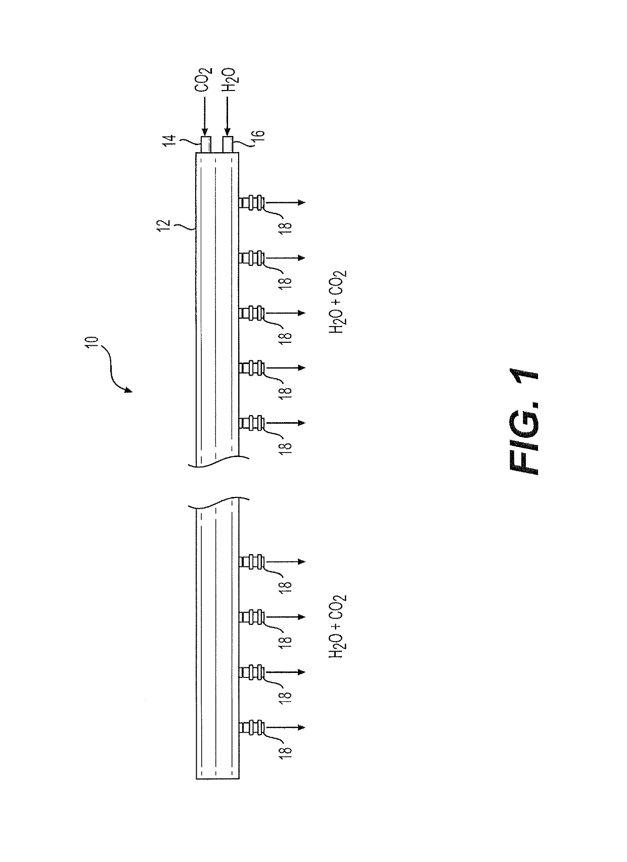
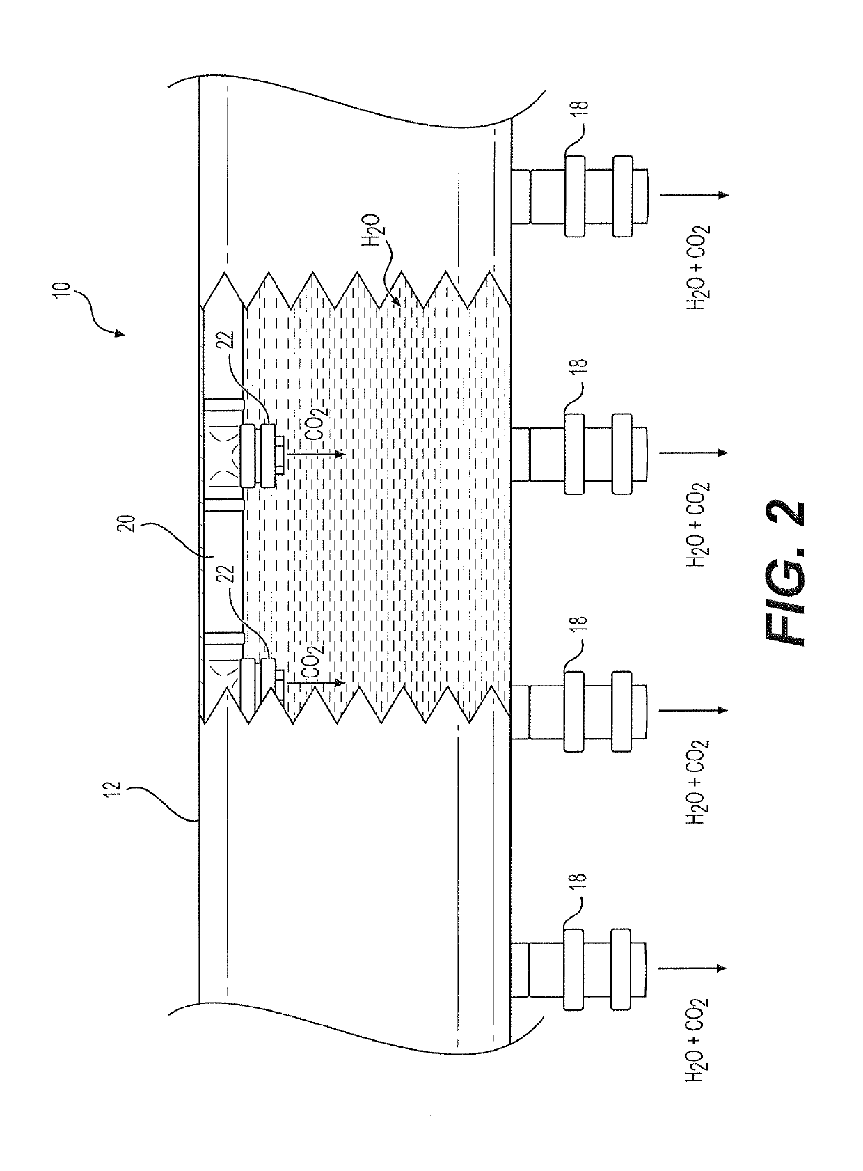
[0010]As shown in FIG. 1, the drip irrigation system 10 includes a pipe 12 having first and second inlets 14, 16, respectively. The first inlet 14 is adapted for receiving pressurized carbon dioxide gas (CO2) from an external source of pressurized carbon dioxide, such as a pressurized tank or the like, and the second inlet 16 is adapted for receiving water (H2O) under pressure from an external source, such as a municipal water supply or the like. It should be understood that the first and second inlets 14, 16, respectively, may include any suitable type of adapter, connector or the like, dependent upon the respective sources of carbon dioxide and water. Pipe 12 may be similar to the water distribution pipe used in conventional drip irrigation systems, although it should be understood that pipe 12 may have any desired relative dimensions, dependent upon the particular agricultural requirements of drip irrigation system 10. As a non-limiting example, pipe 12 may be a polyvinyl chlorid...


PUM


Abstract

The drip irrigation system allows for the irrigation of soil with carbon dioxide-infused water. The drip irrigation system includes a pipe having first and second inlets. The first inlet is adapted for receiving pressurized carbon dioxide gas, and the second inlet is adapted for receiving water under pressure. A plurality of drip nozzles are mounted to the pipe, such that each drip nozzle is in fluid communication with an interior of the pipe. An inner tube is mounted in the interior of the pipe and is in fluid communication with the first inlet for receiving the pressurized carbon dioxide gas. The pressurized carbon dioxide is expelled through a plurality of ports of the inner tube to mix with the water flowing within the interior of the pipe. This mixture forms water infused with carbon dioxide, which is then released, in the forms of drops, by the plurality of drip nozzles.

Description

BACKGROUND1. Field[0001]The disclosure of the present patent application relates to soil irrigation, and particularly to a drip irrigation system which releases water infused with carbon dioxide.2. Description of the Related Art[0002]Drip irrigation is a type of micro-irrigation with the potential to save water and nutrients by allowing water to drip slowly to the roots of plants, either from above or below the soil surface. The goal of drip irrigation is to place water directly into the root zone and minimize evaporation. Drip irrigation systems distribute water through a network of valves, pipes, tubing and emitters. Due to the network of conduits and other components involved in drip irrigation, maintaining adequate pressure in drip irrigation systems can be difficult. Inadequate or uneven pressure throughout the system can result in poor and / or uneven water distribution to the soil.[0003]Further, most drip irrigation systems only supply water to the soil. Any additional additive...

Claims


Application Information

Patent Timeline
Patent Type & Authority Patents(United States)
IPC IPC(8): A01G25/06A01G25/02A01C23/04
CPCA01G25/06A01G25/02A01C23/042A01G7/02Y02A40/22
Inventor KSIKSI, TAOUFIKPPOYIL, SHAIJAL BABU THRUALMARZOOQI, ABDULLA YOUSIF ABDULLA M.BARAHIM, SOLTAN ABDOLLAH
Owner UNITED ARAB EMIRATES UNIVERSITY
Why Eureka
Try Eureka