[0006]It surprisingly appears that one may effectively use UV radiation to substantially prevent biofouling on surfaces that are in contact with sea water or water in lakes, rivers, canals, etc. Herewith, an approach is presented based on optical methods, in particular using ultra-violet light or radiation (UV). It appears that most micro-organisms are killed, rendered inactive or unable to reproduce with sufficient UV light. This effect is mainly governed by the total dose of UV light. A typical dose to kill 90% of a certain micro-organism is 10 mW / h / m2. However, in most of these embodiments, there may be some UV radiation that may reach places it is not intended to go. This basically covers everything above the waterline, and especially human beings in close proximity to the aquatic application. During cruise at open sea, this may not happen (even though it is to be mentioned that personnel on board of the vessel might still face a (tiny) risk), but while e.g. being docked in a harbor the risk is larger, as more people move near the boat. This can include dock workers, crane operators, supply vessels mooring near the ship (on the non-dock side), etc.
[0019]A strong germicidal effect is provided by the light in the short-wave UVC band. In addition erythema (reddening of the skin) and conjunctivitis (inflammation of the mucous membranes of the eye) can also be caused by this form of light. Because of this, when germicidal UV-light lamps are used, it is important to design systems to exclude UVC leakage and so avoid these effects. In case of immersed light sources, absorption of UV light by water may be strong enough that UVC leaking is no problem for humans above the liquid surface. Hence, in an embodiment the UV radiation (anti-fouling light) comprises UVC light. In yet another embodiment, the UV radiation comprises radiation selected from a wavelength range of 100-300 nm, especially 200-300 nm, such as 230-300 nm. Hence, the UV radiation may especially be selected from UVC and other UV radiation up to a wavelength of about 300 nm. Good results are obtained with wavelengths within the range of 100-300 nm, such as 200-300 nm.
[0023]In both general embodiments, the UV emitting element is configured to irradiate with said UV radiation (during an irradiation stage) water adjacent to said part of said external surface. In the embodiments wherein the module itself forms in fact the external surface, the UV emitting element is at least configured to irradiate with said UV radiation (during an irradiation stage) said part of said external surface, as it is in fact part of said external surface, and optionally also water adjacent to said part of said external surface. Hereby, biofouling may be prevented and / or reduced.
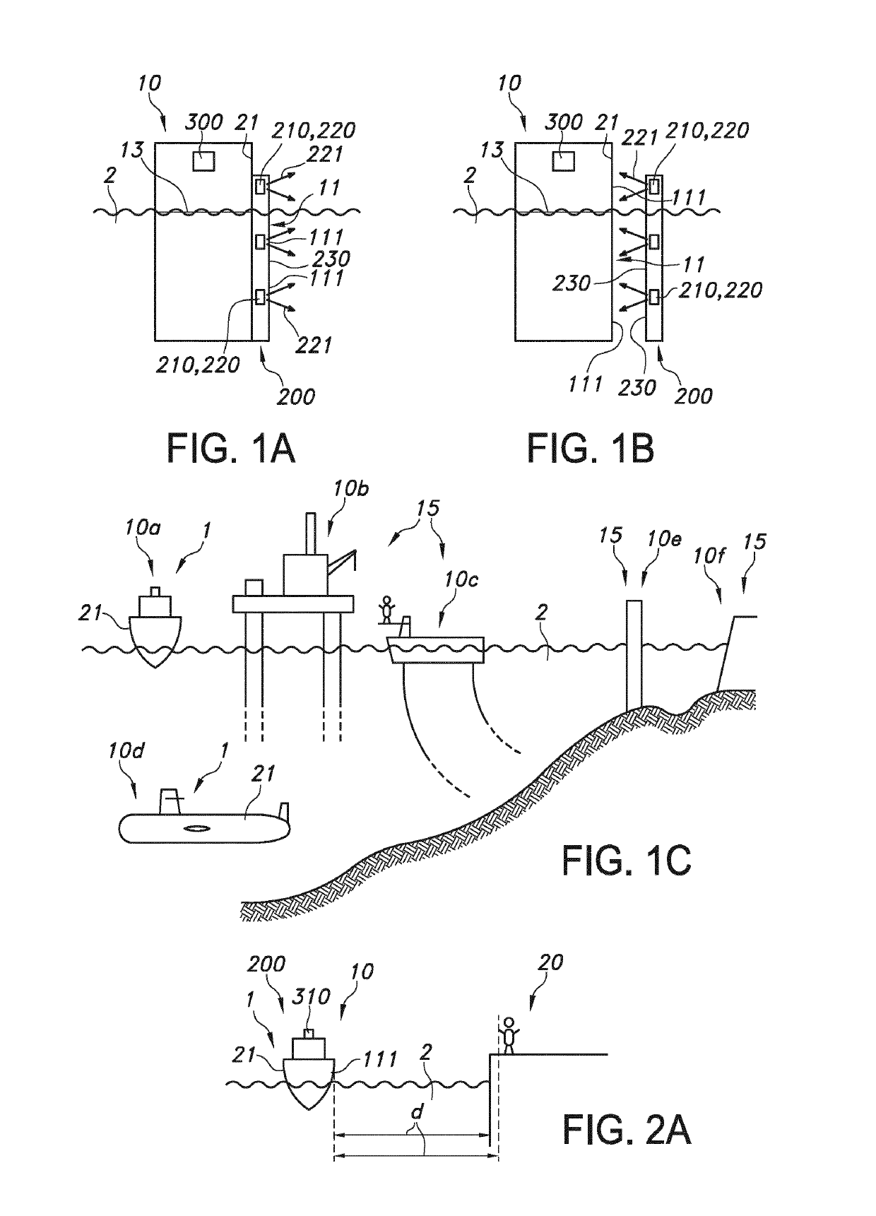
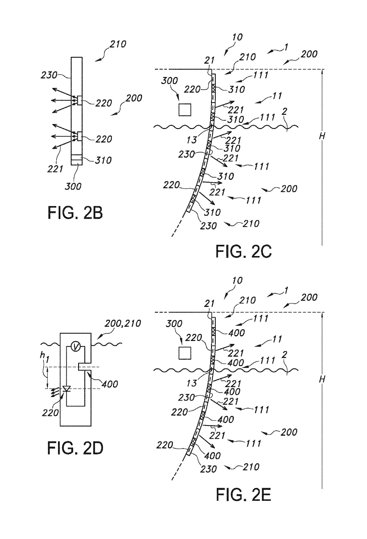
[0036]A relative simple way to reduce the risk of undesired UV radiation exposure of humans may be apply UV radiation only below the water (line). Hence, in an embodiment the control system is configured to control the UV emitting element to the first UV radiation level when one or more of the part and the UV radiation escape surface are below the water (line), and to the second UV radiation level when one or more of the part and the UV radiation escape surface are above the water (line). This may include the use of one or more of (i) a sensor configured to sense the water (line), and (ii) information about loading. Based thereon, the control system may decide whether or not the UV radiation can be applied or will be applied substantially only to the part of the external surface that is below the water (line). Note that in this embodiment there may still be a plurality of variants as the radiation may in general then only be applied when the part is below the water (line), but optionally the UV radiation escape surface may be above the water (line), or also below the water (line). In the latter variant, risk may even be further minimized. Hence, especially the control system is configured to control the UV emitting element to the first UV radiation level when the UV radiation escape surface is below the water (line) and to the second UV radiation level when the UV radiation escape surface is above the water (line). Alternatively or additionally, especially in an embodiment the control system is configured to control the UV emitting element to the first UV radiation level when the part (and the UV radiation escape surface is below the water (i.e. especially the water line), and to the second UV radiation level when the part is above the water (i.e. especially the water line). When using a sensor configured to sense the water, such sensor may be configured close to the radiation escape surface, but configured higher, such as at least 10 cm higher, especially at least 20 cm higher, such as in the range of 10-100 cm higher, like 20-50 cm higher (relative to the object during use) than said surface. In this way, the UV radiation may only be generated when the sensor, and thus the radiation escape surface, is below the water (line) (see further also below). In this way, it may thus be guaranteed that UV light will only be emitted at least e.g. 50 cm below the waterline; which is sufficient to absorb a substantial part of the light. Depending on the absolute intensity of the ‘on’ level, a lower or higher value than 50 cm may be designed, such as to achieve an inherently safe system.
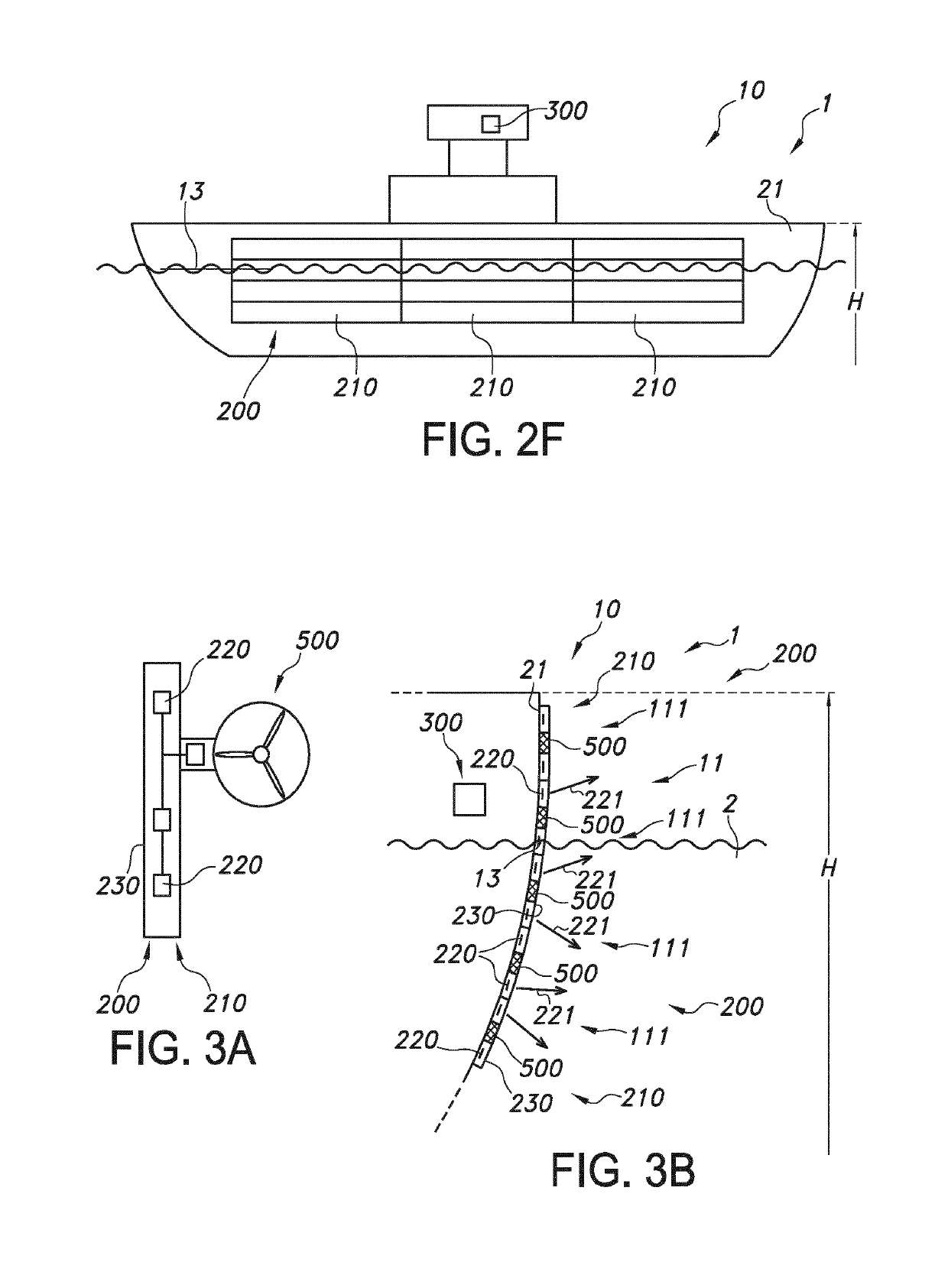
[0057]In a specific embodiment, the UV emitting element comprises a luminescent material configured to absorb part of the UV radiation and convert into visible luminescent material light (i.e. visible light generated by the luminescent material upon excitation with the UV radiation), wherein the light source and said luminescent material are configured to provide said visible luminescent material light emanating in a direction away from the external surface. Optionally, the anti-biofouling system is configured to provide said luminescent material light in a pulsed way. Hence, in this way, a person at a distance from the object (and thus external from the object) may perceive the luminescence, e.g. a red blinking light.
[0066]In an embodiment the lighting module comprises a two-dimensional grid of light sources for generating UV radiation and the optical medium is arranged to distribute at least part of the UV radiation from the two-dimensional grid of light sources across the optical medium so as to provide a two-dimensional distribution of UV radiation exiting the light emitting surface of the light module. The two-dimensional grid of light sources may be arranged in a chicken-wire structure, a close-packed structure, a rows / columns structure, or any other suitable regular or irregular structure. The physical distance between neighboring light sources in the grid may be fixed across the grid or may vary, for example as a function of light output power required to provide the anti-fouling effect or as function of the location of the lighting module on the protected surface (e.g. location on the hull of a ship). Advantages of providing a two-dimensional grid of light sources include that the UV radiation may be generated close to the areas to be protected with UV radiation illumination, and that it reduces losses in the optical medium or light guide and that it is increasing homogeneity of the light distribution. Preferably, the UV radiation is generally homogeneously distributed across the emission surface; this reduces or even prevents under-illuminated areas, where fouling may otherwise take place, while at the same time reducing or preventing energy waste by over-illumination of other areas with more light than needed for anti-fouling. In an embodiment, the grid is comprised in the optical medium. In yet another embodiment, the grid may be comprised by a (silicone) foil.

