High voltage fringe-effect capacitor

a fringe-effect capacitor and high-voltage technology, applied in the direction of anti-noise capacitors, feed-through capacitors, fixed capacitor details, etc., can solve the problems of limiting the useful bandwidth of the capacitor, reducing the service life of the capacitor, so as to increase the overall capacitance and the operational bandwidth of the multi-layer chip capacitor. , the effect of increasing the capacitan

Active Publication Date: 2019-04-16
PRESIDIO COMPONENTS
View PDF12 Cites 1 Cited by
  • Summary
  • Abstract
  • Description
  • Claims
  • Application Information

AI Technical Summary

Benefits of technology

[0018]In one embodiment of the invention, a multilayer chip capacitor includes electrodes comprised of numerous, closely spaced conductive layers interposed within a dielectric laminate. The conductive layers are configured in such a way that the multilayer chip capacitor obtains substantially all of its capacitance from fringe capacitance between opposing electrodes. This construction allows for higher breakdown voltages and capacitor values in a smaller physical package.
[0019]In another embodiment of the invention, the conductive layers of a multilayer chip capacitor are configured so that the gap between electrodes of opposite polarity traverses the dielectric laminate body in such a way so as to form a non-planer boundary between electrodes. This may increase the effective surface area of the electrodes, which in turn may increase the capacitance of the capacitor.
[0021]In another embodiment of the invention, an additional high frequency integrated capacitor is formed from external electrode plates, which increases both the overall capacitance and the operational bandwidth of a multilayer chip capacitor.

Problems solved by technology

Realizable capacitors deviate from this ideal relationship due to series resistance and series inductance, which are unavoidable byproducts of the physical configuration of the capacitor as well as the properties of the materials used to make the capacitor.
However, as operational frequencies increase, the equivalent series resistance and equivalent series inductance begin to dominate the device impedance, which limits useful bandwidth of the capacitor.
As can be seen, because of the required electrode spacing, it becomes very difficult to maintain high voltage ratings with conventional designs in a multilayer chip capacitor as the exterior dimensions shrink.
When the electrodes of a filter capacitor are subjected to these high voltages, which with safety margins may be thousands of volts, capacitors having partially overlapping electrode plates are subject to developing voltage breakdown paths.
Due to the large electrode plate separations required to prevent this voltage breakdown, high voltage capacitors having high capacitive values are difficult to produce in a small form factor, particularly in the case of multilayer chip capacitors.
Discoidal feed-through capacitors, on the other hand, have been found to be prone to cracking when used in implanted cardiac pacemakers because the metal wire travels though the center of the capacitor.
Discoidal feed-through capacitors also have an inconvenient form factor as compared to chip capacitors.

Method used


Image

  • High voltage fringe-effect capacitor
  • High voltage fringe-effect capacitor
  • High voltage fringe-effect capacitor

Examples


Embodiment Construction

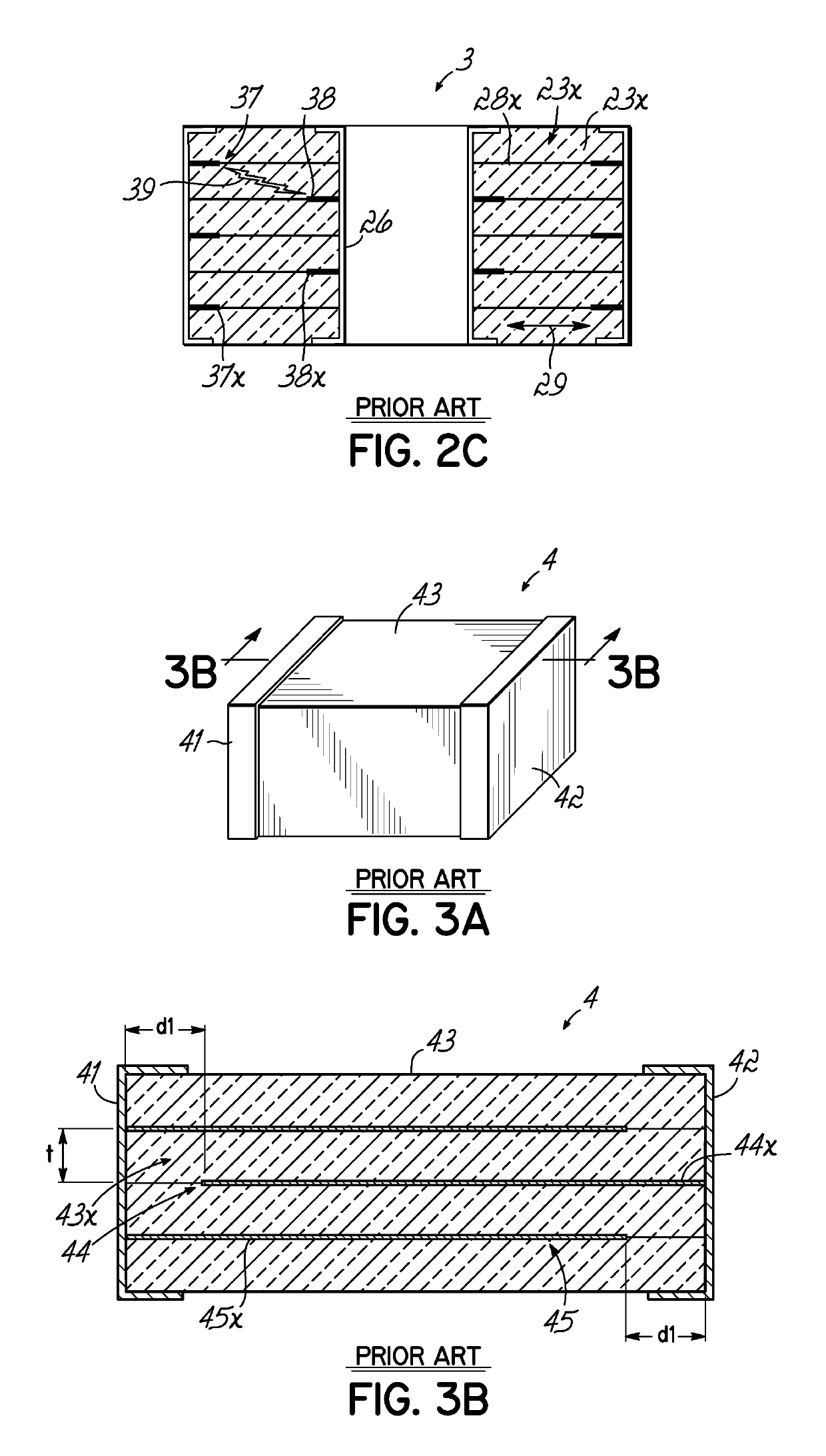
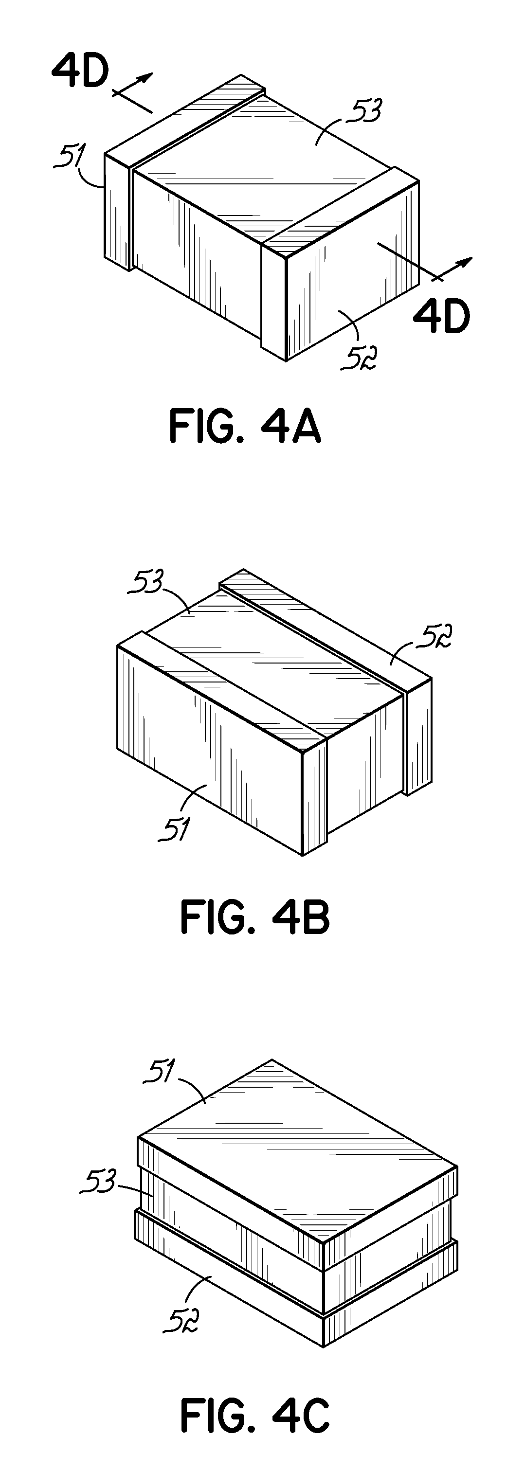
[0060]Turning to the drawings of the embodiments of the invention, wherein like numbers denote like parts throughout the several views, FIGS. 4A-4E are diagrams showing multiple embodiments of the invention where non-overlapping electrodes are used to form multilayer chip capacitors 5, 6. Fringe-effect capacitance is a term used to describe capacitance attributable to the electrostatic fields that build up at the edge of electrode plates. Fringe-effect capacitance is always present between the edge of an electrode plate and a conductor having an opposite polarity. An example of a fringe-effect capacitance is the capacitance that may exist between the far ends of electrode plates 44x, 45x and their respective opposing electrically conductive terminals 42, 41 in FIG. 3B. Fringe-effect capacitance accounts for only a fraction of the capacitance of the standard multilayer chip capacitor 4 because of the high aspect ratio of electrode plate 44x, 45x length to dielectric layer 43x thickne...


PUM


Abstract

A multilayer chip capacitor includes electrodes comprised of numerous, closely spaced conductive layers interposed within a dielectric laminate. Adjacent conductive layers are essentially non-overlapping, so that fringe capacitance between opposing electrodes provides substantially all of the capacitance. The conductive layers may be shaped to form a non-planer boundary between electrodes. An additional high frequency integrated capacitor is formed from external electrode plates. The non-planar electrode boundary principle is also applied to discoidal capacitors in the form of a non-concentric electrode boundary.

Description

RELATED APPLICATIONS[0001]This application is a divisional of U.S. application Ser. No. 12 / 965,557 filed Dec. 10, 2010, now allowed, and which is hereby incorporated by reference herein in its entirety.TECHNICAL FIELD[0002]The present invention generally concerns high voltage capacitors. More particularly, the present invention concerns the configuration of the electrodes in a multilayer capacitor forming part of a high bandwidth, high voltage filter capacitor.BACKGROUND[0003]The present invention relates to the design of multilayer filter capacitors made of a dielectric material such as a ceramic dielectric material. A capacitor is an electronic component that stores electrical energy in the form of an electric field, and is commonly used for filtering and energy storage applications in electronic circuits. The electric field forms between electrically opposed electrodes when a voltage is applied to the capacitor terminals. An ideal capacitor is characterized by the equation:i=C×dv...

Claims


Application Information

Patent Timeline
Patent Type & Authority Patents(United States)
IPC IPC(8): H01G4/35H01G4/005H01G4/30H01G4/012
CPCH01G4/30H01G4/005H01G4/012H01G4/35H01G4/232
Inventor TRINH, HUNG VANDEVOE, ALAN
Owner PRESIDIO COMPONENTS
Why Eureka
Try Eureka