Multi-phase clock generation employing phase error detection in a controlled delay line

a delay line and multi-phase clock technology, applied in the direction of automatic control, electrical equipment, etc., can solve the problems of consuming relatively large power, reducing the efficiency of multi-phase clocks, and reducing the use of frequency dividers. , to achieve the effect of reducing the number of delay circuits, and reducing the cost of operation

Active Publication Date: 2019-04-23
QUALCOMM INC
View PDF22 Cites 1 Cited by
  • Summary
  • Abstract
  • Description
  • Claims
  • Application Information

AI Technical Summary

Benefits of technology

[0004]Current efforts to provide high-frequency (e.g., multiple tens of gigahertz) clocks have focused on DLLs. Error detection is accomplished by lowering the base frequency and using more delay circuits. The low frequency makes error detection easier, and the long chain of delay circuits allows the final combined clock signal to be at the desired high frequency. However, use of large strings of delay circuits consumes valuable space and adds to the power consumption. Thus, there needs to be a way to provide high-frequency multi-phase clocks without incurring the space or power penalties of traditional designs.

Problems solved by technology

With clock frequencies in the megahertz (MHz) range and even up into the low gigahertz (GHz) range, conventional multi-phase clock generation circuits provided acceptable performance, but as clock speeds are moving into the millimeter range (e.g., around 30 GHz), traditional designs have become less acceptable.
For example, frequency dividers need high-frequency clock sources and consume relatively large amounts of power.
Given the power constraints of some mobile computing devices, such power use is an unacceptable design tradeoff.
Phase interpolation has a limited range, and its accuracy at high frequencies is not sufficiently precise for current designs.
PLLs typically use a frequency divider, and thus suffer the same limits that frequency dividers suffer.
At high frequencies, detection of the errors is difficult because the errors may be in the low picosecond range.
However, use of large strings of delay circuits consumes valuable space and adds to the power consumption.

Method used


Image

  • Multi-phase clock generation employing phase error detection in a controlled delay line
  • Multi-phase clock generation employing phase error detection in a controlled delay line
  • Multi-phase clock generation employing phase error detection in a controlled delay line

Examples


Embodiment Construction

[0022]With reference now to the drawing figures, several exemplary aspects of the present disclosure are described. The word “exemplary” is used herein to mean “serving as an example, instance, or illustration.” Any aspect described herein as “exemplary” is not necessarily to be construed as preferred or advantageous over other aspects.

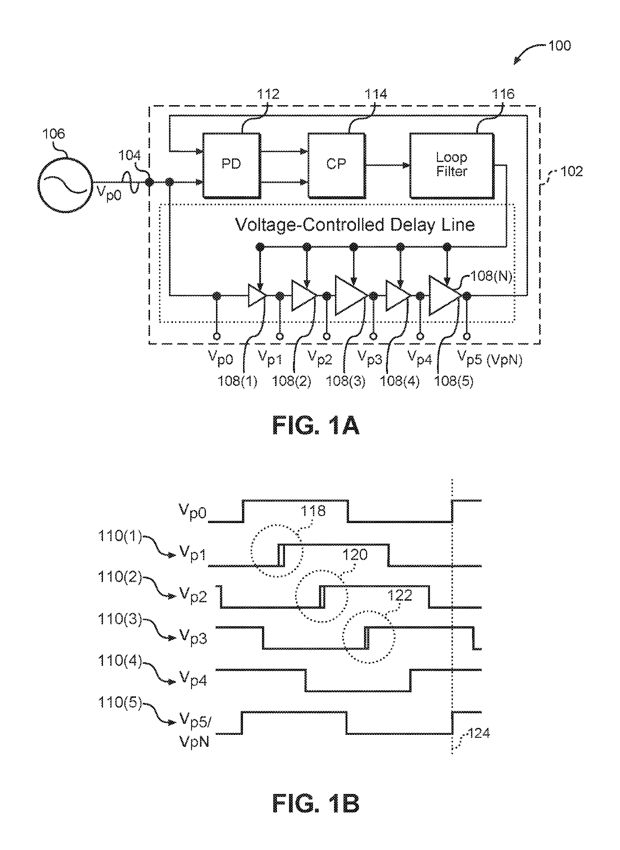
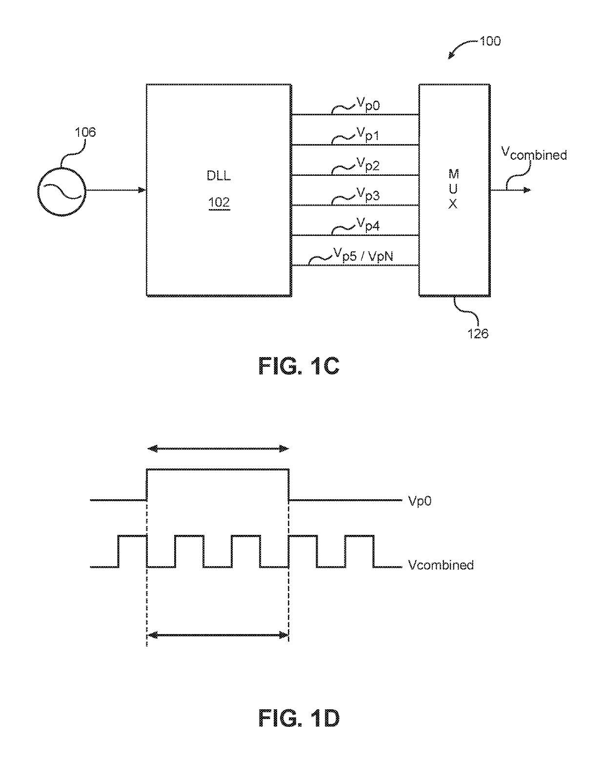
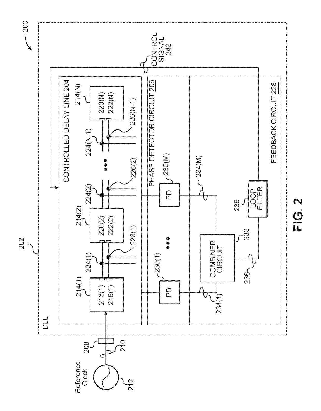
[0023]Aspects disclosed herein include multi-phase clock generation employing phase error detection between multiple delay circuit outputs in a controlled delay line to provide error correction. In exemplary aspects disclosed herein, a multi-phase clock generator is provided that includes a controlled delay line and a phase error detector circuit. As an example, the multi-phase clock generator can provide a multi-phase clock for use in millimeter wave frequency ranges while having a relatively small footprint and consuming relatively low amounts of power. The controlled delay line is configured to receive a reference clock signal. The controlled delay...


PUM


Abstract

Multi-phase clock generation employing phase error detection between multiple delay circuit outputs in a controlled delay line to provide error correction is disclosed. A multi-phase clock generator is provided that includes a controlled delay line and a phase error detector circuit. Tap nodes are provided from outputs of one or more delay circuits in the controlled delay line. To detect and correct for phase errors in the controlled delay line, a phase detection circuit is provided that includes at least two phase detectors each configured to measure a phase offset error between tap nodes from the delay circuit(s) in the controlled delay line. These phase errors are then combined to create an error correction signal, which is used to control the delay of the delay circuit(s) in the controlled delay line to lock the phase of the output of the final delay circuit to an input reference clock signal.

Description

BACKGROUNDI. Field of the Disclosure[0001]The technology of the disclosure relates generally to multiple-phase (multi-phase) clocks that generate multiple clock signals offset in phases and, more particularly, to phase error detection and correction of multi-phase clock signals.II. Background[0002]Computing devices have become increasingly common in modern society. The abundance of these devices may be attributed, in part, to the myriad functions such devices provide and the speed with which such functions are provided. The speed with which functions are accomplished is based, in part, on the speed of clocks used to drive the timing of synchronous circuitry. Different frequencies of clock signals can drive circuits to control their speed of operation. Multiple (multi-) phase clocks including multiple clock signals offset in phases are also useful in many applications. For example, in high-speed serial link applications, multi-phase clocks can be used to process data streams at a bit...

Claims


Application Information

Patent Timeline
Patent Type & Authority Patents(United States)
IPC IPC(8): H03L7/06H03L7/087H03L7/081
CPCH03L7/087H03L7/0812H03L2207/12
Inventor SUN, BO
Owner QUALCOMM INC
Why Eureka
Try Eureka