
Scheduling request procedure

a request procedure and scheduling technology, applied in the field of scheduling request procedure, can solve the problems of wasting resources, not being able to configure mobile terminals, and not being able to find a spectrum band which is wide enough for the lte-advanced system, so as to improve the procedure of requesting uplink resources and flexibly delay the triggering or transmission

Active Publication Date: 2019-04-23
PANASONIC INTELLECTUAL PROPERTY CORP OF AMERICA
View PDF5 Cites 6 Cited by
  • Summary
  • Abstract
  • Description
  • Claims
  • Application Information

AI Technical Summary

Benefits of technology

This approach reduces power consumption by minimizing unnecessary transitions to active state, thereby extending battery life and improving resource management efficiency in LTE systems.

Problems solved by technology

Nowadays, the lack of radio spectrum has become a bottleneck of the development of wireless networks, and as a result it is difficult to find a spectrum band which is wide enough for the LTE-Advanced system.
It may currently not be possible to configure a mobile terminal with more uplink component carriers than downlink component carriers.
For example, in case of a web browsing service, it is usually a waste of resources for a UE to continuously receive downlink channels while the user is reading a downloaded web page.
The reason for introducing the logical channel group concept is that even though the UE may have more than four logical channels configured, reporting the buffer status for each individual logical channel would cause too much signaling overhead.
However, the above procedure basically repeats itself as illustrated, with the exception that the PUSCH transmission, including the BSR and the data, does not suffice to empty the transmission buffer.
The frequent transmission of scheduling requests will obviously increase the power consumption of the user equipment and also increases the load on the scheduling request channel, as well as the number of PDCCH grants in response to the received scheduling requests.
Furthermore, the UE shall not have sufficient uplink resources to transmit a buffer status report to the eNodeB.

Method used


Image

  • Scheduling request procedure
  • Scheduling request procedure
  • Scheduling request procedure

Examples


Embodiment Construction

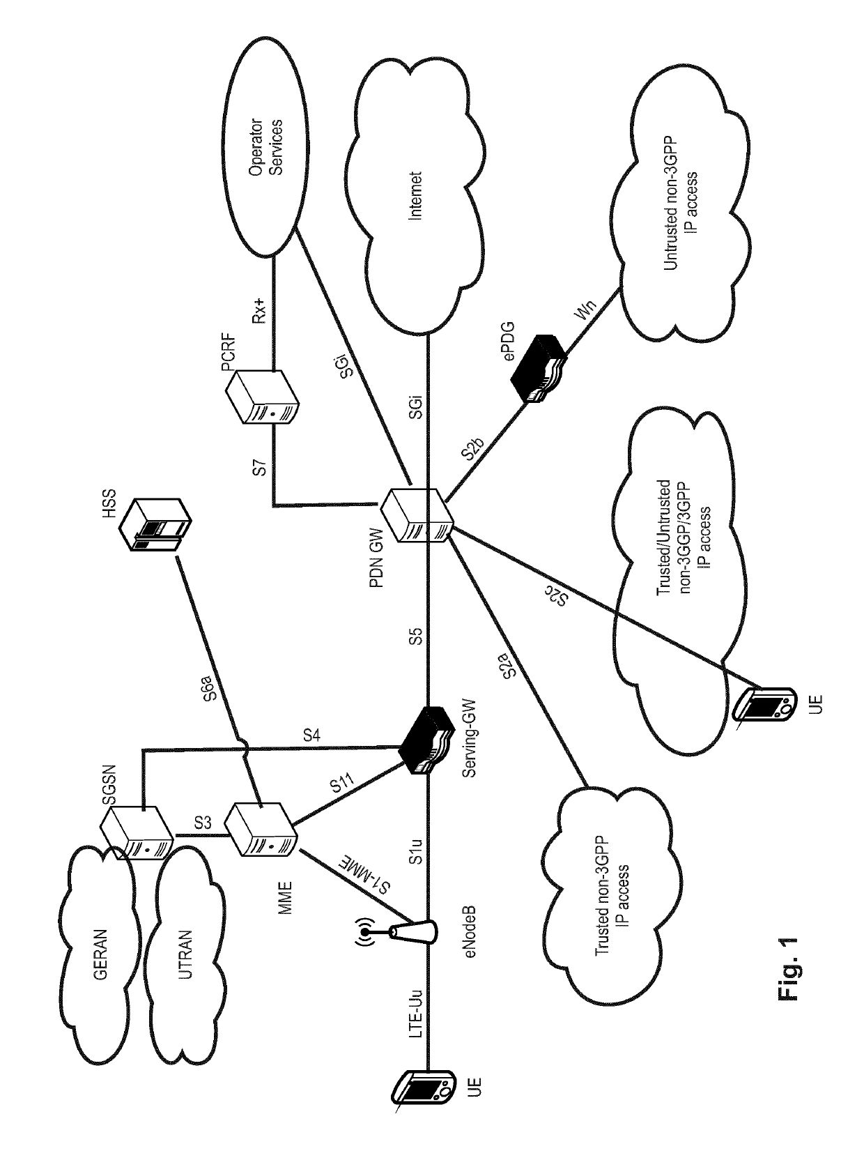
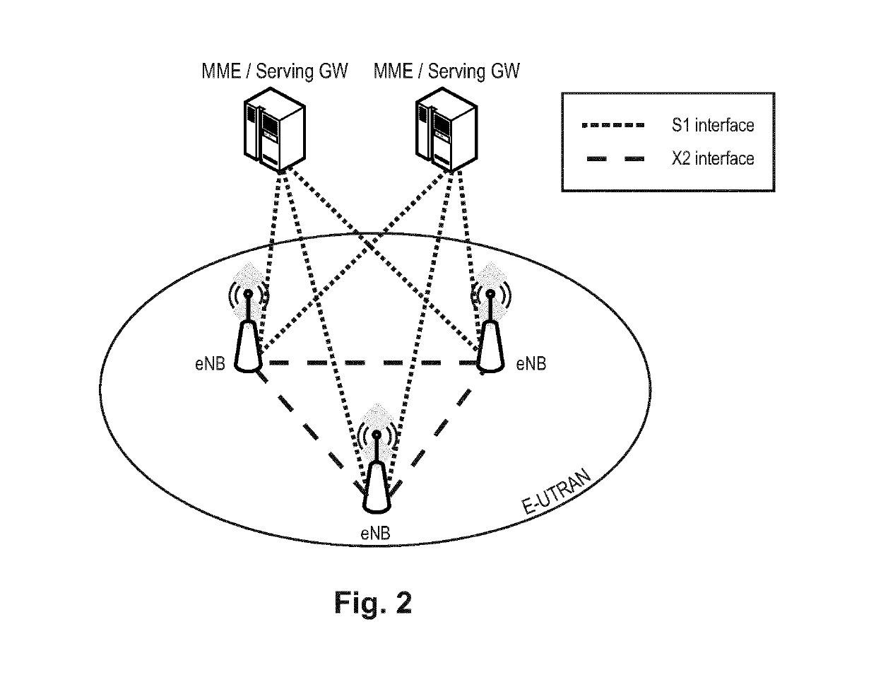
[0171]It should be noted that the embodiments may be advantageously used, for example, in a mobile communication system such as 3GPP LTE-A (Release 10 / 11 / 12) communication systems as described in the Description of the Related Art section above, but the embodiments are not limited to its use in this particular exemplary communication networks.

[0172]A mobile station or mobile node or user terminal is a physical entity within a communication network. One node may have several functional entities. A functional entity refers to a software or hardware module that implements and / or offers a predetermined set of functions to other functional entities of a node or the network. Nodes may have one or more interfaces that attach the node to a communication facility or medium over which nodes can communicate. Similarly, a network entity may have a logical interface attaching the functional entity to a communication facility or medium over which it may communicate with other functional entities ...


PUM


Abstract

The invention relates to a method for requesting uplink resources by a user equipment in a communication system, wherein a DRX, Discontinued Reception, function is running at the user equipment. The transmission of a scheduling request for requesting uplink resources to a radio base station is triggered upon triggering of a buffer status report in the user equipment. However, the triggering of the scheduling request is delayed such that the scheduling request is triggered in one of the subframes—preferably the first subframe—of an On-Duration period of a DRX cycle according to the DRX function. Correspondingly, the triggered scheduling request is transmitted to the radio base station in the next possible scheduling request transmission occasion after the triggering of the scheduling request is delayed.

Description

BACKGROUND[0001]Technical Field[0002]The present disclosure relates to methods for requesting uplink resources by a user equipment in a communication system. The present disclosure is also providing the user equipment for participating in the methods described herein.[0003]Description of the Related ArtLong Term Evolution (LTE)[0004]Third-generation mobile systems (3G) based on WCDMA radio-access technology are being deployed on a broad scale all around the world. A first step in enhancing or evolving this technology entails introducing High-Speed Downlink Packet Access (HSDPA) and an enhanced uplink, High Speed Uplink Packet Access (HSUPA), giving a radio access technology that is highly competitive.[0005]In order to be prepared for further increasing user demands and to be competitive against new radio access technologies, 3GPP introduced a new mobile communication system, which is called Long Term Evolution (LTE). LTE is designed to meet the carrier needs for high speed data and ...

Claims


Application Information

Patent Timeline
Patent Type & Authority Patents(United States)
IPC IPC(8): H04W72/12H04W28/02H04W52/02H04W76/28H04W88/02H04W88/08
CPCH04W72/1284H04W28/0278H04W52/0206H04W52/0251H04W76/28H04W88/02H04W88/08Y02D70/00Y02D70/1242Y02D70/1244Y02D70/1246Y02D70/1262Y02D70/1264Y02D70/21Y02D70/23Y02D70/24Y02D30/70H04W72/21
Inventor LOEHR, JOACHIMBASU MALLICK, PRATEEK
Owner PANASONIC INTELLECTUAL PROPERTY CORP OF AMERICA
Learn More