
Adaptive shadow control system for a surgical lighting system

a technology of shadow control and lighting system, which is applied in the field of surgical lighting system, can solve the problems of limited shadow control, excess lighting capability limited to the lighting partition, and limited adjustment of light output, so as to achieve less excess light output capacity, less complexity, and improved shadow control

Active Publication Date: 2019-04-23
AMERICAN STERILIZER CO
View PDF31 Cites 5 Cited by
  • Summary
  • Abstract
  • Description
  • Claims
  • Application Information

AI Technical Summary

Benefits of technology

The present invention provides an adaptive shadow control system that can compensate for blockage of a first lighthead using increased light output from a second lighthead. It also improves shadow control and provides a full lighthead to compensate for loss of illumination due to blockage of another lighthead in the lighting system. It allows lightheads to be configured with less excess light output capacity and to have less complexity and can be automatically enabled when it is detected that multiple lightheads are used in conjunction with each other in a "co-illumination" mode. It includes enable / disable control logic which uses asynchronous operation of each lighthead of a lighting system to determine whether the respective light beams of multiple lightheads are being aggregated for co-illumination at a single location in a work area.

Problems solved by technology

Such blockage is commonly caused by the presence of a person's head (e.g., a surgeon or surgical assistant) located between the lighthead and the work area.
In prior art surgical lighting systems, shadow control is limited to adjusting the light intensity of the lighting partitions in a single lighthead due to a blockage incurred with respect to that same lighthead.
Accordingly, excess lighting capability is limited to the lighting partitions of the unblocked regions of a single lighthead.
Furthermore, adjustment of light output is limited to the number of unique lighting partitions within the lighthead, wherein the light intensity of each lighting partition is independently controlled.
However, such an increase in the number of partitions results in a significant increase in engineering complexity, electrical inefficiency, lighthead size, and manufacturing cost.

Method used


Image

  • Adaptive shadow control system for a surgical lighting system
  • Adaptive shadow control system for a surgical lighting system
  • Adaptive shadow control system for a surgical lighting system

Examples


Embodiment Construction

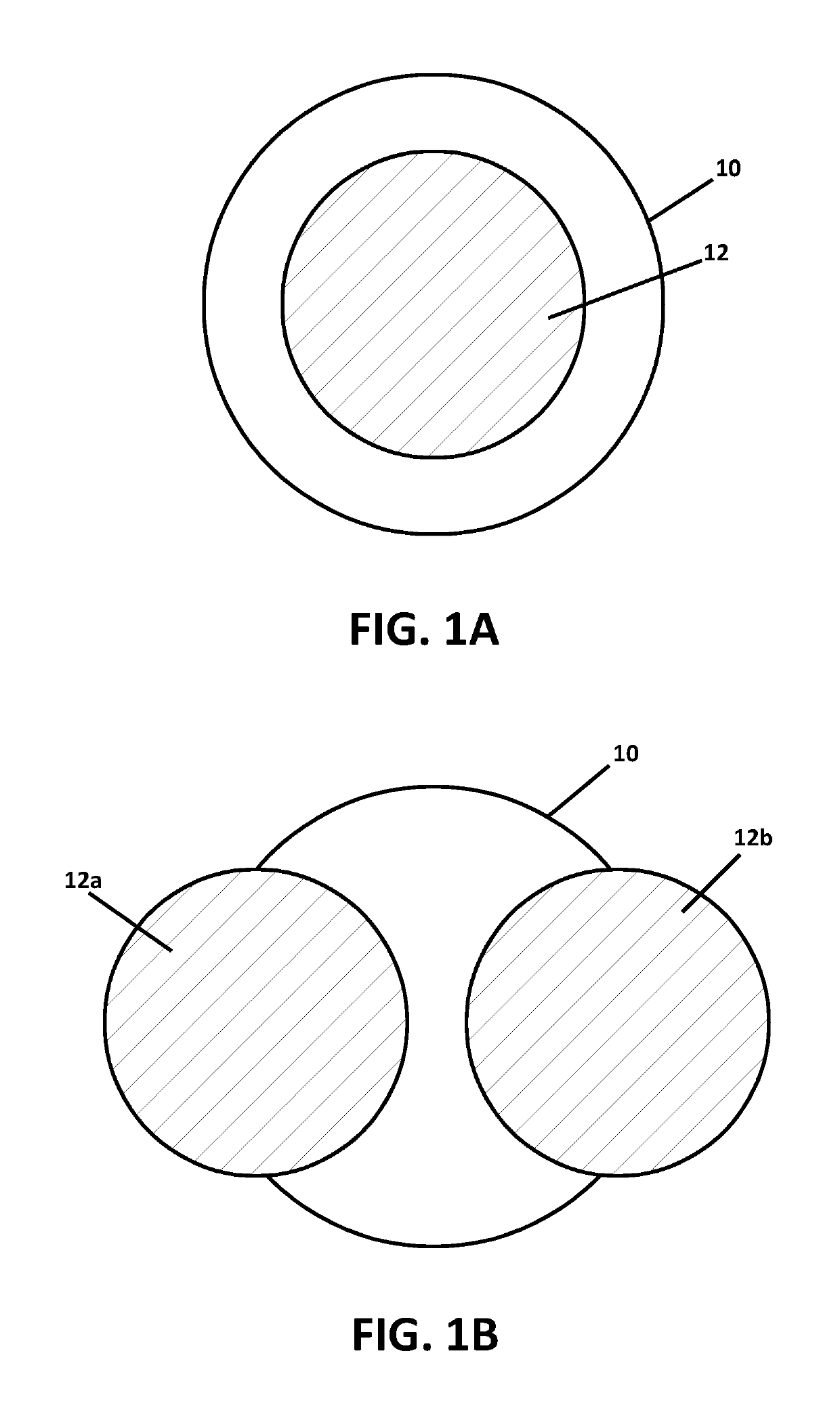
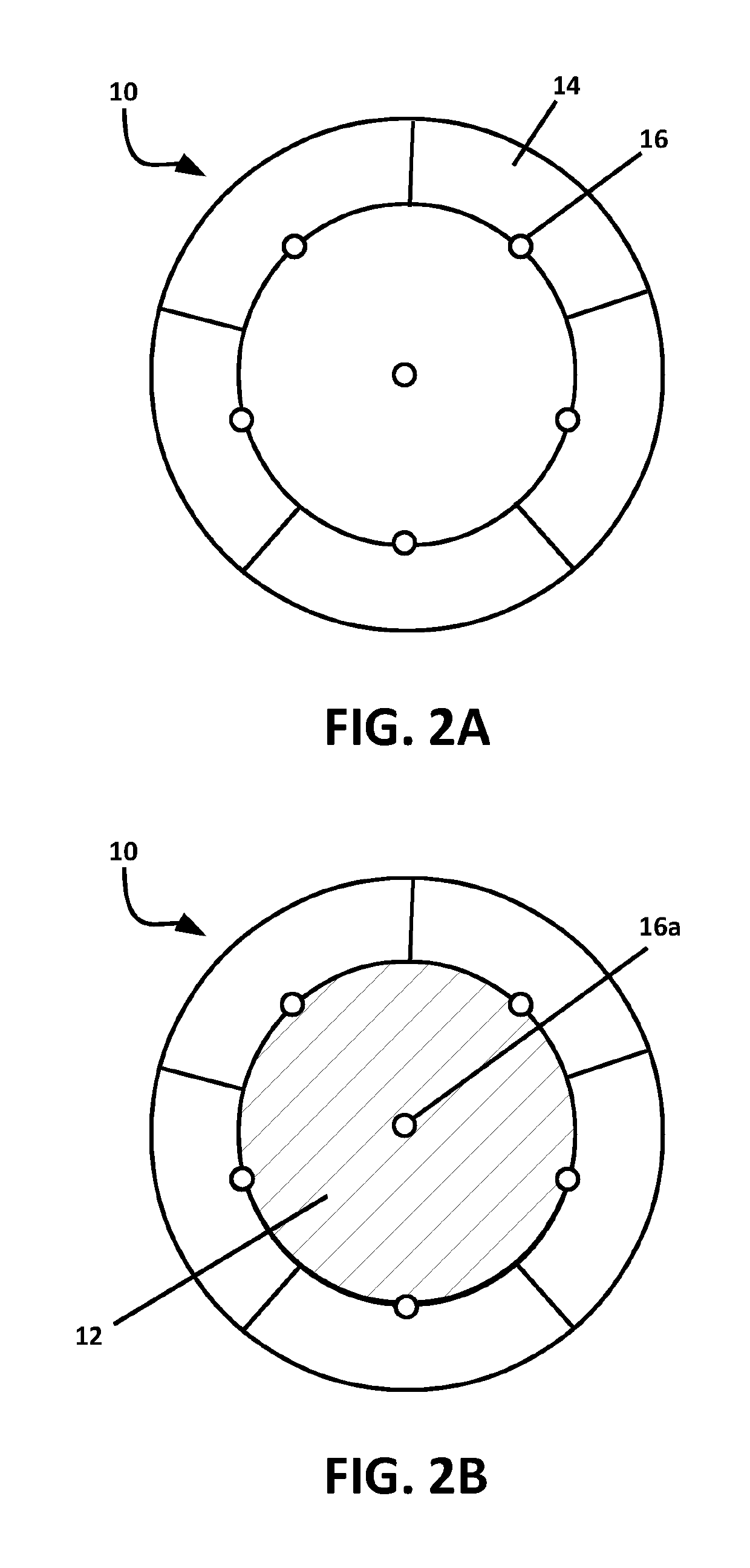
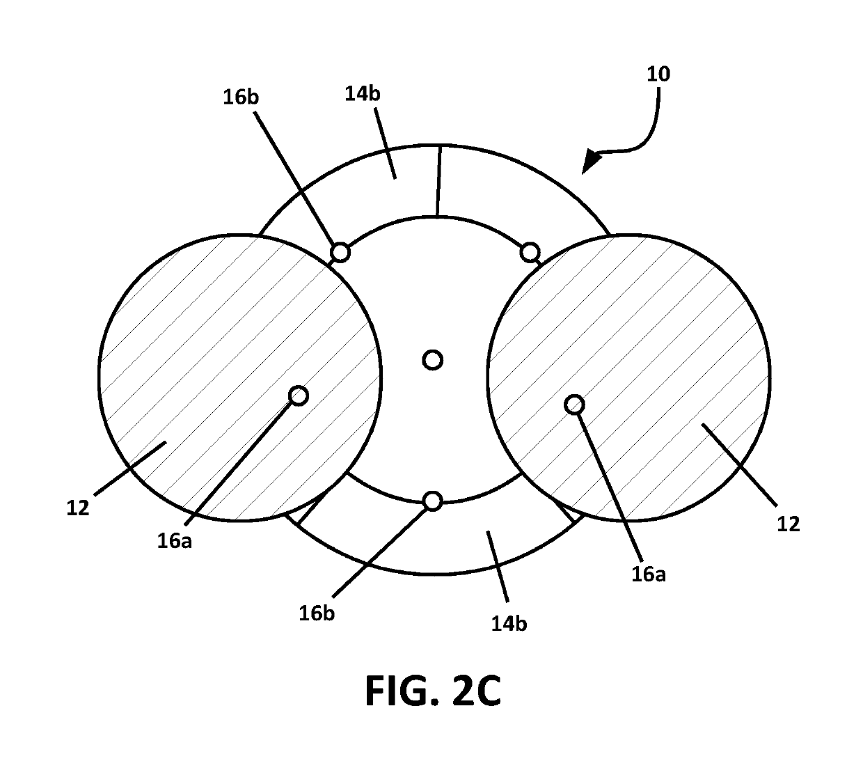
[0041]Referring now to the drawings wherein the showings are for the purposes of illustrating an embodiment of the invention only and not for the purposes of limiting same, the present invention is directed to an adaptive shadow control system for a surgical lighting system. As shown in FIG. 3, a lighting system 20 is comprised of two lightheads 30, 40 where each lighthead 30, 40 includes at least one lighting module having one or more light elements, which can be LEDs. The lightheads 30, 40 illuminate a work area (e.g., a surgical site of a surgical patient supported by a surgical table 50). In accordance with an embodiment of the present invention, sensor assemblies 32, 42, are associated with each respective lighthead 30, 40 (e.g., mounted to the lighthead housing) to detect whether there is a blockage, between the lighthead and the work area, that is blocking at least a portion of the associated light beam emitted by one or both of the lightheads 30, 40. The sensor assemblies 32...


PUM


Abstract

An adaptive shadow control system that compensates for blockage of one lighthead of a surgical lighting system by increasing the light output from one or more other lightheads of the lighting system. The system also includes control logic for automatic enablement / disablement of adaptive shadow control by detecting whether there is blockage of a lighthead and whether the respective light beams of a plurality of lightheads are being aggregated to form a single aggregated co-illumination light pattern at a work area.

Description

RELATED APPLICATIONS[0001]This application claims the benefit of U.S. Provisional Application No. 62 / 415,595, filed Nov. 1, 2016, said provisional application is hereby fully incorporated herein by reference.FIELD OF THE INVENTION[0002]The present invention relates generally to surgical lighting systems, and more particularly to an adaptive shadow control and co-illumination control for a surgical lighting system.BACKGROUND OF THE INVENTION[0003]The present invention relates to the field of surgical lighting systems and problems associated therewith. In one aspect, shadow control is an important element of lighting system performance because it minimizes the contrast of shadow edges cast and minimizes reductions in illumination due to lighthead blockage, thereby providing a uniform lighting field having consistent light intensity. A typical surgical lighting system includes at least one surgical lighthead (also referred to as a “luminaire”), wherein each lighthead is formed of a plu...

Claims


Application Information

Patent Timeline
Patent Type & Authority Patents(United States)
IPC IPC(8): H05B33/08A61B90/30H05B44/00
CPCH05B33/0854A61B90/30H05B33/0842A61B2090/309A61B2017/00154A61B2017/00057H05B45/00H05B45/12H05B47/115H05B47/17H05B47/155
Inventor HOLLOPETER, MICHAELJESURUN, DAVID
Owner AMERICAN STERILIZER CO
Learn More