
Humidifier unit

a technology of humidifier and humidifier body, which is applied in the direction of respirator, lighting and heating apparatus, domestic heating, etc., can solve the problems of water vapour being taken up by the air flow, risk of water spillage into the rpt device or the patient, and achieve the effect of simple and cost-effective humidifier structur

Active Publication Date: 2019-04-30
FOOTE ROGER
View PDF13 Cites 1 Cited by
  • Summary
  • Abstract
  • Description
  • Claims
  • Application Information

AI Technical Summary

Benefits of technology

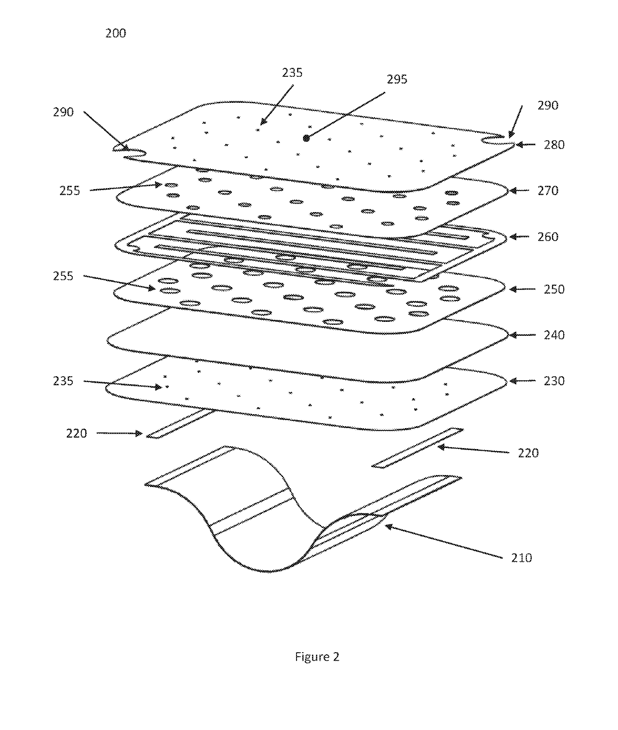
[0014]In a first broad form, the present invention provides a wick for a humidifier, which includes an internal heating element and which receives water from below via a wicking action. This enables a simple, cost effective humidifier structure in suitable implementations.
[0015]According to one aspect, the present invention provides a multilayer humidifier wick, including at least a top layer, a bottom layer, and a heating element intermediate the top and bottom layer, the top and bottom layer being hydrophilic and in communication so that water will pass from the bottom layer to the top layer by a wicking action, such that operatively the bottom layer passes water through the heating element to the top layer, and the heating element increases the temperature of the water in the wick.
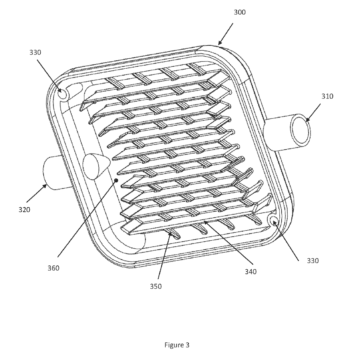
[0016]According to another aspect, the present invention provides a humidifier for a flow of air, including a reservoir adapted to retain water, a lid, an air inlet and an air outlet, and a wick positioned over the reservoir, the wick including at least a top layer, a bottom layer, and a heating element intermediate the top and bottom layer, the top and bottom layer being hydrophilic and in communication so that water will pass from the bottom layer to the top layer by a wicking action, such that operatively the bottom layer passes water through the heating element to the top layer, and the heating element increases the temperature of the water in the wick, and so that operatively the humidity of a flow of air passing from the inlet to the outlet is increased.
[0022](d) Passing the air flow across an upper surface of the wick, so that the humidity of the air flow is increased.
[0024]Implementations of the present invention allow for a simple, relatively inexpensive humidifier to be provided. The simplicity and ready manufacturability of the wick, according to suitable implementations of the present invention, allow for easy and cost effective manufacture, and simple assembly and operation.

Problems solved by technology

If this flow of air is not humidified, the patient's airways can dry out, causing discomfort to the patient.
The air flow from the RPT device passes over the heated water in the water tub, resulting in water vapour being taken up by the air flow.
Such a humidifier configuration presents a number of drawbacks.
There is a risk of spillage of the volume of water into the RPT device or to the patient.
A drawback with such wick systems is that the water reservoir is generally at ambient pressure and the water is fed by pump to the wick which is enclosing the pressurized air flow.

Method used


Image

  • Humidifier unit
  • Humidifier unit
  • Humidifier unit

Examples


Embodiment Construction

[0030]The present invention will be described in more detail with reference to specific implementations. However, it will be appreciated that these are intended as illustrative of the application of the present invention, and not limitative of the scope.

[0031]In particular, the present invention will be described primarily in the context of an RPT or CPAP machine, intended to deliver a flow of air to a patient in the context of sleep apnoea and similar conditions. However, the present invention is applicable wherever a flow of air, optionally including medical gases or other materials, is to be delivered to a patient, and humidification is desired. For simplicity, the term ‘air’ is used in the specification and claims as a general term to include air alone, oxygen, and other medical gases admixed with air or otherwise. The invention should not be considered as limited to any particular field of use, and can be used to humidify an air flow of any desired type.

[0032]The present invent...


PUM


Abstract

A low cost medical humidifier for adding moisture to a patient air flow is disclosed. The humidifier comprises a water reservoir, a disposable evaporative wick containing a heater, a lid containing electrical contacts to engage the heater in the wick and airway connections. The wick heater comprises a PET film with aluminum tracks and a cover layer of PTC resistive ink. The heater is covered with paper to provide a water pathway via capillary flow. There is a capillary path from the water reservoir to the wick. The wick and heater are manufactured with printing and calendaring processes in reel to reel processes.

Description

CROSS REFERENCE TO RELATED APPLICATIONS[0001]This Non-provisional Application is a 35 U.S.C. Sect. 371 National Stage entry of PCT / AU2016 / 050428 entitled “MEDICAL HUMIDIFIER”, filed May 31, 2016 and claims the benefit of Australian Application No. 2016203593, filed May 30, 2016 which claims the benefit of Australian Application No. 2015902098 filed on Jun. 2, 2015, the entireties of which are incorporated herein by reference.TECHNICAL FIELD[0002]The present invention relates to the production of humidified air for use with medical devices. In particular, the present technology relates to the humidification of air intended to be inhaled by a patient. However, it will be appreciated that the invention is not limited to this field of use.BACKGROUND OF THE INVENTION[0003]The following discussion of the prior art is provided to place the invention in an appropriate technical context and enable the advantages of it to be more fully understood. It will be appreciated, however, that any dis...

Claims


Application Information

Patent Timeline
Patent Type & Authority Patents(United States)
IPC IPC(8): F24F6/02A61M16/14A61M16/10A61M16/00A61M16/16F24F6/10
CPCA61M16/16A61M16/0066A61M16/109A61M16/142F24F6/10F24F6/02A61M2205/3653A61M16/107A61M16/161A61M2205/3368
Inventor FOOTE, ROGER
Owner FOOTE ROGER
Learn More