
Nucleic acid amplification method

a nucleic acid and serpentine channel technology, applied in the direction of fermentation, biochemistry apparatus and processes, microbiological testing/measurement, etc., can solve the problems of reducing the thermal capacity of the heater or the chamber itself, slow temperature control, and affecting the quality of the sample, so as to minimize the analytical volume, the effect of advantageous characteristic features and high sensitivity

Active Publication Date: 2019-04-30
NAT INST OF ADVANCED IND SCI & TECH
View PDF16 Cites 0 Cited by
  • Summary
  • Abstract
  • Description
  • Claims
  • Application Information

AI Technical Summary

Benefits of technology

[0038]There is a demand for the realization of a system capable of examining the presence or absence of a gene from a minimal amount of a biological sample collected in medical practice, as in genetic testing with high sensitivity. Here, microfluidic devices have advantageous characteristic features in that they use minimized analytical volume and achieve maximized heat transfer efficiency with an increase in the surface area relative to the volume. The use of these features is necessary to establish a technique for high-speed minimal-volume gene amplification. Unlike the existing method in gene-amplification technique, i.e., PCR, the present invention uses the morphology (form) of sample plugs separated by air to use the vapor pressure of the sample solution itself. By using vapor pressure produced at the interface between the front of the sample plug and air, and vapor pressure produced at the interface between the back of the sample plug and air, the present invention can achieve both high speed and excellent efficiency, which have been unsolved problems of known continuous-flow PCR using a flat-plate type microfluidic device. The present invention thus has features such that it requires no additional special external device and contributes to minimization of the sample volume and speeding up of a continuous-flow PCR, with maximum use of the advantages of the microfluidic device.

Problems solved by technology

However, in a generally used thermal cycling device used in PCR, the temperature control is slow due to the huge thermal capacity of the aluminum block heater; thus, the PCR procedure requires 1 to 2 hours for 30 to 40 cycles.
Even when the latest genetic testing device is used, the analysis requires a total of several hours.
Although the purpose of this method is to speed up thermal cycling by reducing the sample amount to reduce the thermal capacity, the reduction in the thermal capacity of the heater or chamber itself is limited, and at least about 30 seconds is required per cycle to sufficiently perform the amplification reaction; therefore, even with the use of the highest-speed device, 15 minutes or longer must be spent to complete the PCR reaction.
However, a number of integrated valves and pumps are used to introduce the sample and pump it through the temperature zones in a rotary fashion; thus, downsizing the device is difficult (Patent Document 3).
However, this system has not yet been put to practical use, as it suffers from problems such as the flow frequently being stopped due to air bubbles randomly formed at a heating zone.
However, such a continuous flow requires a large amount of PCR sample, and complicated controls.
Further, air bubbles are easily formed at the denaturation temperature zone at 95° C., frequently causing the disturbance and stopping of the flow.
Moreover, the sample solution passes through several meters of a microtube or micro-flow channel to repeatedly move through each temperature zone about 30 to 40 times; thus, the fluid resistance becomes large as the flow speed becomes slow, preventing efficient and rapid temperature control from being achieved.
However, a quick and simple PCR that can be performed on-site is not available with current technology, and a method for ultra-rapidly performing amplification has been in demand.

Method used


Image

  • Nucleic acid amplification method
  • Nucleic acid amplification method
  • Nucleic acid amplification method

Examples


Embodiment Construction

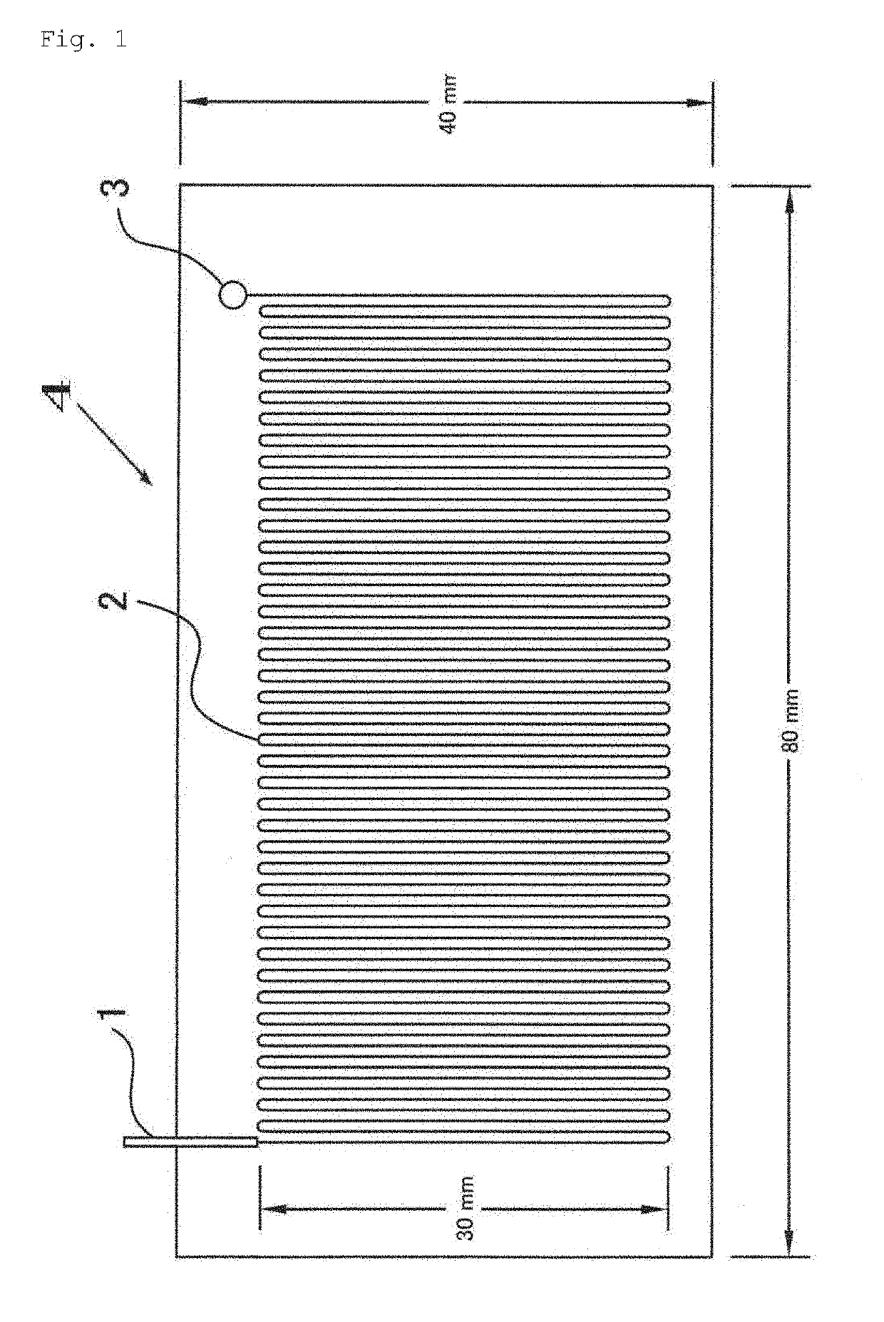
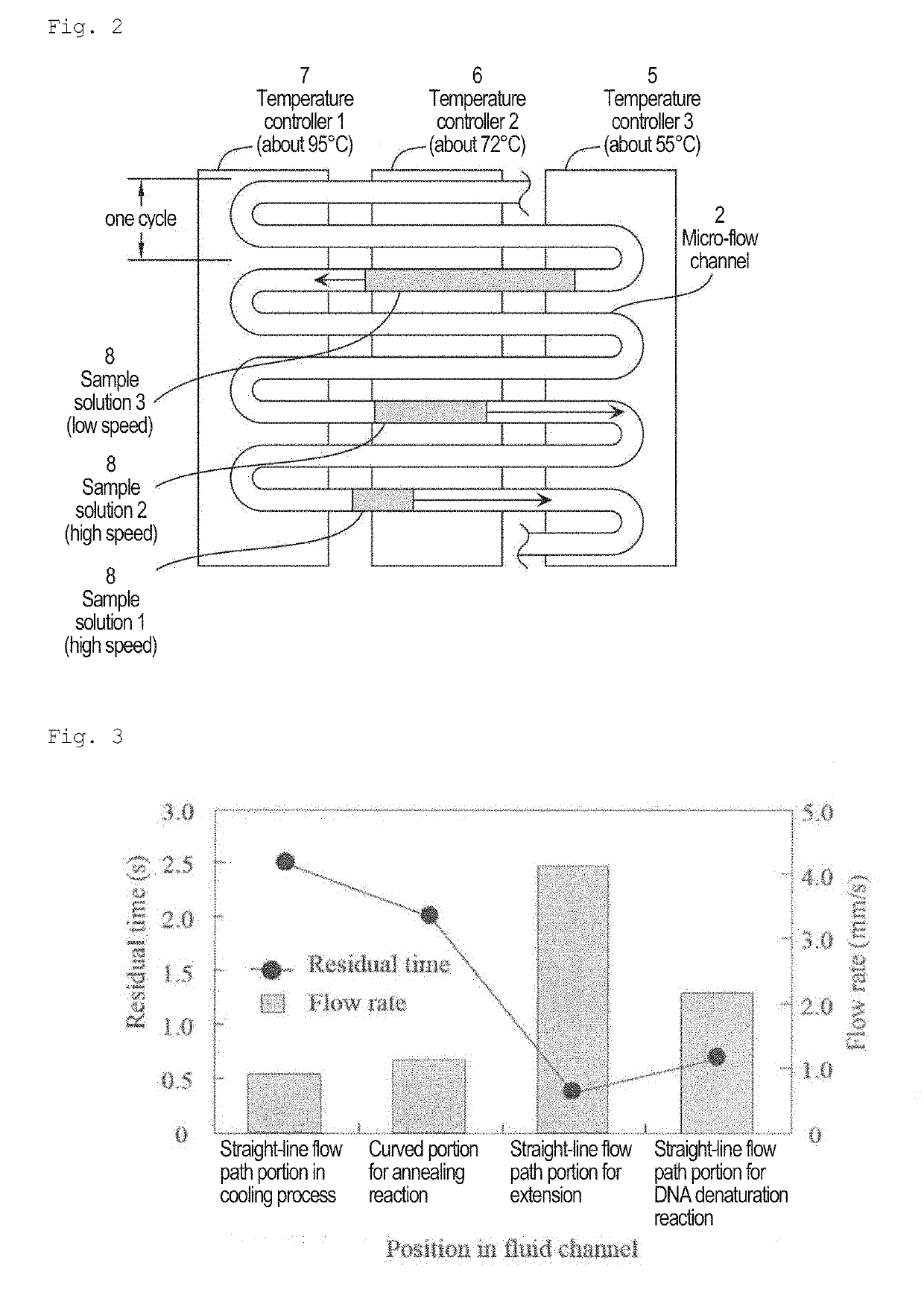
[0049]The present invention relates to a nucleic acid amplification method using a very high-speed polymerase chain reaction (PCR) in a micro-flow channel, which repeatedly passes through a plurality of temperature zones in a meandering manner. More specifically, an object of the present invention is to provide a method using a micro-flow channel in a flat-plate type microfluidic system for continuous-flow PCR, provided with a flow channel design for accurately controlling the temperature of a PCR sample flowing as sample plugs separated by air by and appropriately set flow conditions thereby performing ultra-rapid nucleic acid amplification in the flow channel.

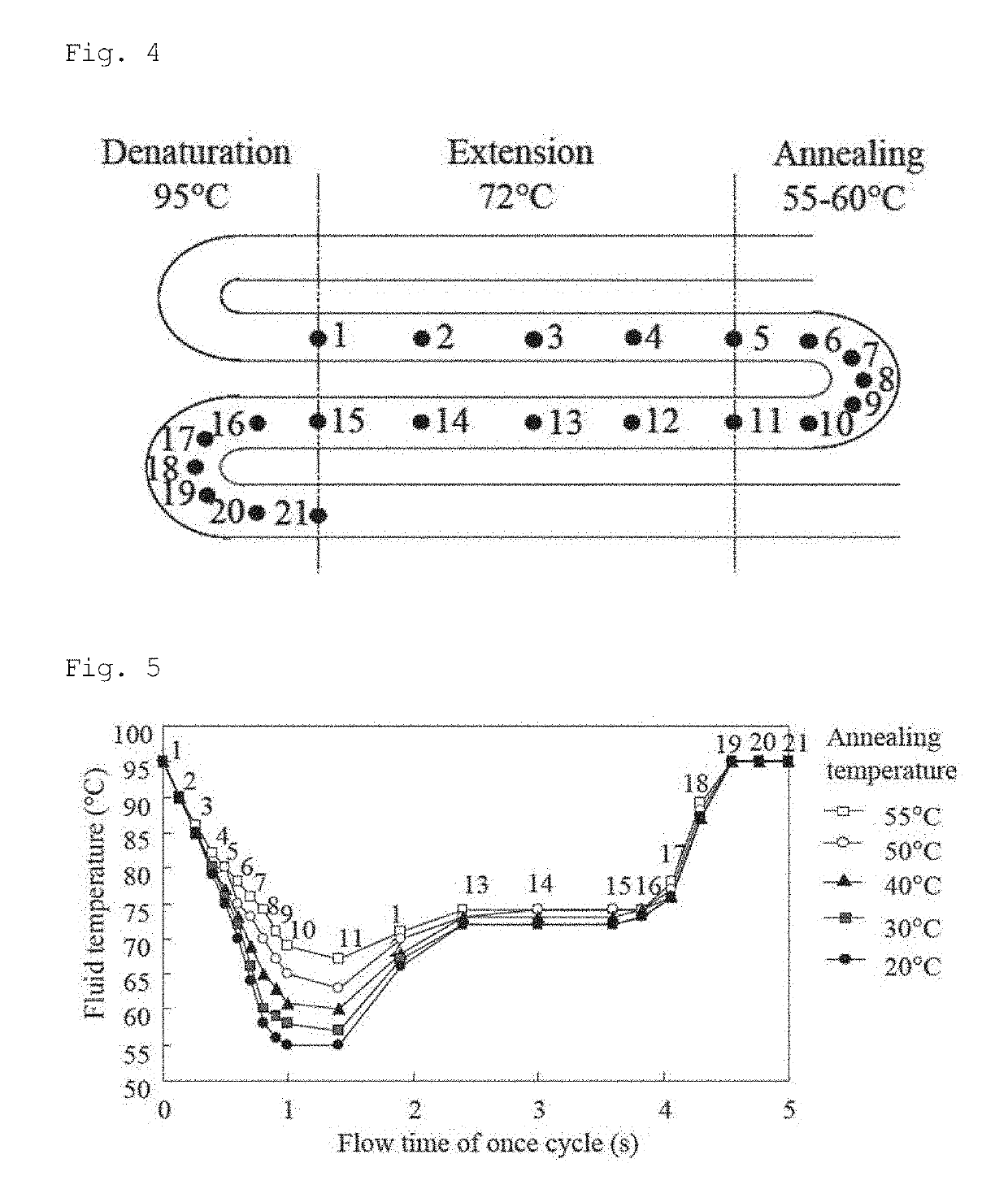
[0050]In this specification, a plurality of temperature zones indicates a DNA denaturation temperature zone, an annealing temperature zone, and an extension temperature zone. It is possible for these three temperature zones to be clearly distinguished from each other by a heating device (heater) or a cooling device. It is als...


PUM

PropertyMeasurementUnit
temperatureaaaaaaaaaa
cross-sectional aspect ratioaaaaaaaaaa
aspect ratioaaaaaaaaaa

Abstract

The invention provides an ultra-rapid nucleic acid amplification method performed in a flow channel. Specifically, the invention provides a nucleic acid amplification method for performing a PCR reaction by supplying a PCR sample solution to a nucleic acid amplification device comprising a serpentine channel adapted to perform at least one PCR cycle, the nucleic acid amplification device comprising a DNA denaturation temperature zone corresponding to the curved portions at one side, an annealing temperature zone corresponding to the curved portions at the other side, and an extension temperature zone positioned between the annealing and DNA denaturation temperature zones, wherein the PCR sample solution is introduced in the form of sample plugs separated by gas into the serpentine channel using a pump, the sample solution being supplied into the channel in a state such that the solution is separated by gas into a segment corresponding to one PCR cycle or smaller segments.

Description

CROSS-REFERENCE TO RELATED APPLICATIONS[0001]This patent application is the U.S. national phase of International Patent Application No. PCT / JP2012 / 056079, filed Mar. 9, 2012, which is incorporated by reference in its entirety herein.TECHNICAL FIELD[0002]The present invention relates to a method for ultra-rapid nucleic acid amplification in a serpentine channel. More specifically, the present invention relates to a method that provides flow conditions and a flow channel design for accurately controlling temperature using a continuous-flow microfluidic system, and performs an ultra-rapid polymerase chain reaction (PCR).BACKGROUND ART[0003]Genetic testing has been central to various fields, such as drug development, forensic medicine, clinical tests, and identification of agricultural products or pathogenic microorganisms. Genetic testing serves as a ubiquitous technique for, for example, disease diagnosis and prognosis, marker selection, safety evaluation of food products and environm...

Claims


Application Information

Patent Timeline
Patent Type & Authority Patents(United States)
IPC IPC(8): C12Q1/68C12P19/34C12Q1/686C12Q1/6848
CPCC12Q1/686C12Q1/6848C12Q2565/629C12Q2565/631
Inventor NAGAI, HIDENORIFUCHIWAKI, YUSUKE
Owner NAT INST OF ADVANCED IND SCI & TECH
Learn More