Fuel injection device

a fuel injection device and fuel injection technology, applied in the direction of fuel injection apparatus, machine/engine, charge feed system, etc., can solve the problem of achieve the effect of small surface roughness, large surface roughness, and easy disturbance of fuel flow

Active Publication Date: 2019-05-07
DENSO CORP
View PDF44 Cites 3 Cited by
  • Summary
  • Abstract
  • Description
  • Claims
  • Application Information

AI Technical Summary

Benefits of technology

[0008]As a mode in which the surface roughness of the outlet-channel-forming portion is larger than the surface roughness of the inlet-channel-farming portion, for example, multiple convex portions or concave portions are formed in the outlet-channel-forming portion. In such a case, a flow rate of the fuel is easily maintained when passing through the inlet-channel-forming portion having a relatively small surface roughness. When the fuel passes through the outlet-channel-forming portion having a relatively large surface roughness, the fuel flow is easily disturbed. When the fuel of which flow has been disturbed is injected from the outflow port, the fuel is atomized by being diffused in various directions.

Problems solved by technology

When the fuel passes through the outlet-channel-forming portion having a relatively large surface roughness, the fuel flow is easily disturbed.

Method used


Image

  • Fuel injection device
  • Fuel injection device
  • Fuel injection device

Examples


first embodiment

(First Embodiment)

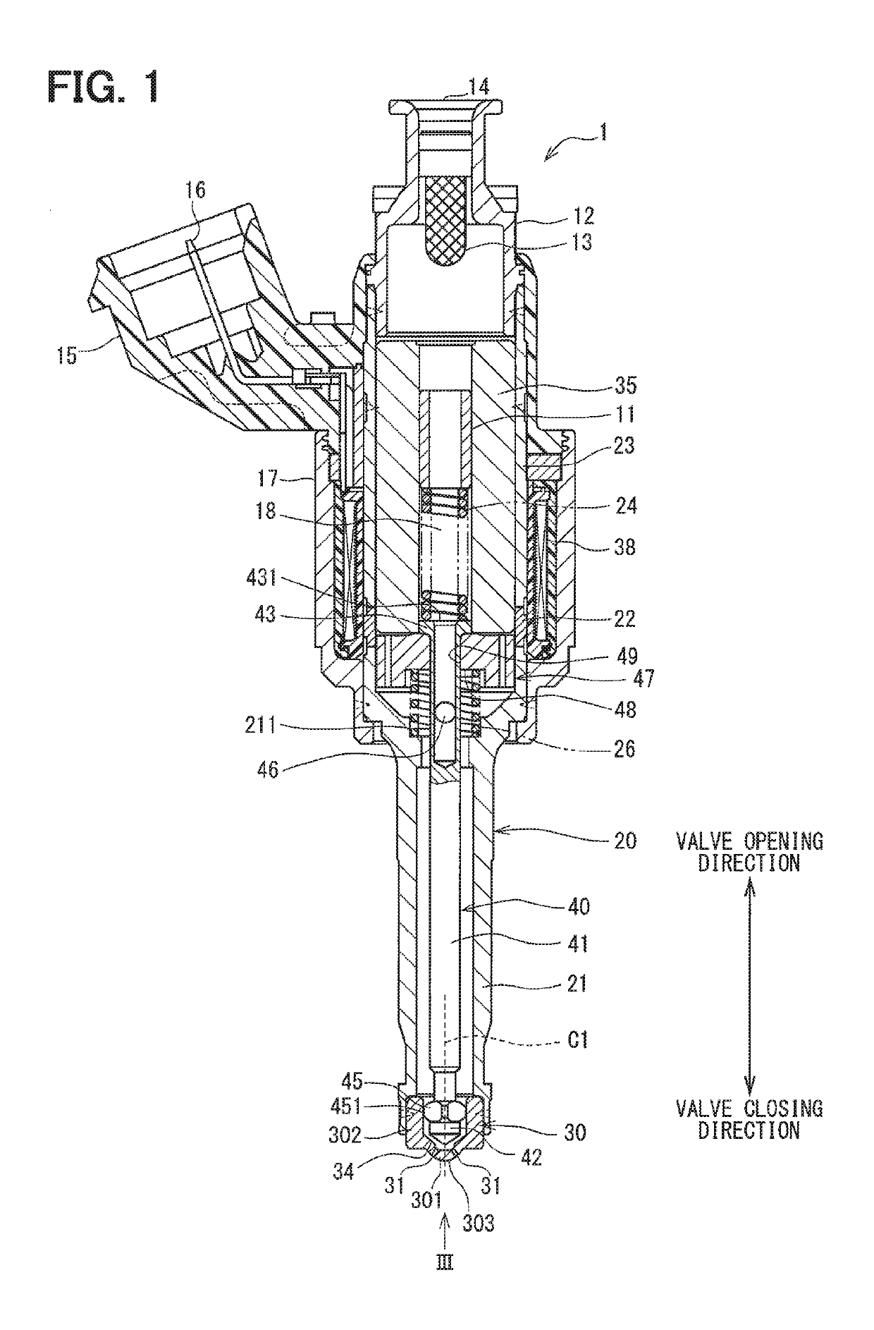
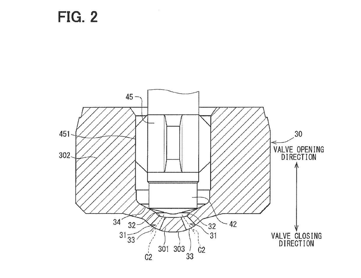
[0034]A fuel injection device 1 according to a first embodiment of the present disclosure is illustrated in FIGS. 1 and 2. FIG. 1 illustrates a valve opening direction that is a direction along which a needle 40 is separated from a valve seat 34 and a valve closing direction along which the needle 40 abuts against the valve seat 34.

[0035]A fuel injection valve 1 is used in, for example, a fuel injection device for a direct injection gasoline engine not shown and injects a gasoline as a fuel into an engine. The fuel injection valve 1 includes a housing 20, the needle 40, a movable core 47, a fixed core 35, a coil 38, springs 24, 26, and so on.

[0036]As illustrated in FIG. 1, the housing 20 includes a first cylinder member 21, a second cylinder member 22, a third cylinder member 23, and a body portion 30. Each of the first cylinder member 21, the second cylinder member 22, and the third cylinder member 23 is formed in a substantially cylindrical shape, and the first c...

second embodiment

(Second Embodiment)

[0086]In the fuel injection device 1 according to the above embodiment, with the provision of the grooves 371 in the outlet-channel-forming portion 351a, the surface roughness of the outlet-channel-forming portion 351a is set to be larger than the surface roughness of the inlet-channel-forming portion 341a. In the present embodiment, with the provision of convex portions on an outlet-channel-forming portion 351a, a surface roughness of the outlet-channel-forming portion 351a is set to be larger than a surface roughness of an inlet-channel-forming portion 341a.

[0087]An appearance of the injection hole 311 according to the present embodiment will be described with reference to FIG. 8. Because the other portions are identical with those in the first embodiment, their description will be omitted.

[0088]As illustrated in FIG. 8, multiple convex portions 381 are formed on the outlet-channel-forming portion 351a of the injection hole 311. For that reason, the surface rou...

third embodiment

(Third Embodiment)

[0092]In the first embodiment and the second embodiment described above, the surface roughness of the outlet-channel-forming portion 351a is set to be larger than the surface roughness of the inlet-channel-forming portion 341a, to thereby promote the atomization. The fuel injection device 1 according to the present embodiment promotes the atomization by setting the diameter expansion ratio of the inlet channel 341 and the outlet channel 351 to be different from each other. In the present embodiment, the surface roughness of the outlet-channel-forming portion 351a is the same as the surface roughness of the inlet-channel-forming portion 341a.

[0093]An appearance of the injection hole 311 according to the present embodiment will be described with reference to FIG. 9. The diameter D1 of the inlet channel 341 is increased, that is, the diameter of the inlet channel 341 is increased along a direction from the inflow port 321 toward the outflow port 331. The diameter D2 ...


PUM


Abstract

In a fuel injection device including a body portion that forms an injection hole through which a fuel is injected, the body portion includes an inlet-channel-forming portion that is connected to an inflow port of the fuel in the injection hole and forms an inlet channel which is a fuel flow channel, and an outlet-channel-forming portion that is connected to the inlet channel and an outflow port of the fuel in the injection hole, and forms an outlet channel that is a fuel flow channel. A surface roughness of the outlet-channel-forming portion is larger than a surface roughness of the inlet-channel-forming portion.

Description

CROSS-REFERENCE TO RELATED APPLICATION[0001]This application is the U.S. national phase of International Application No. PCT / JP2016 / 001665 filed Mar. 23, 2016, which designated the U.S. and claims priority to Japanese Patent Application No. 2015-80286 filed on Apr. 9, 2015 and Japanese Patent Application No. 2015-147790 filed on Jul. 27, 2015, the entire contents of each of which are incorporated herein by reference.TECHNICAL FIELD[0002]The present disclosure relates to a fuel injection device.Embodiments for Carrying out Invention[0003]A fuel injection device that injects a fuel into a cylinder of an internal combustion engine has been known. For example, as illustrated in Patent Literature 1, an injection hole is formed in a fuel injection device, and the fuel is injected from an outflow port of the injection hole.[0004]When the fuel is injected from the outflow port of the injection hole, it is desirable that the fuel is atomized. When the atomization of the fuel is promoted, a f...

Claims


Application Information

Patent Timeline
Patent Type & Authority Patents(United States)
IPC IPC(8): F02M61/00F02M61/14F02M61/18
CPCF02M61/1833F02M61/18F02M61/14
Inventor KATO, NORITSUGUIMAI, KEITA
Owner DENSO CORP
Why Eureka
Try Eureka