Shape compliant gripper
- Summary
- Abstract
- Description
- Claims
- Application Information
AI Technical Summary
Benefits of technology
Problems solved by technology
Method used
Image
Examples
first embodiment
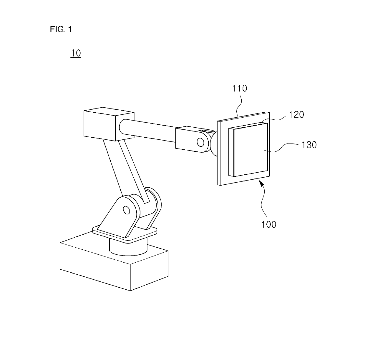
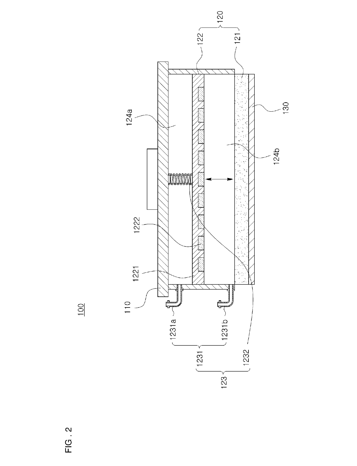
[0039]Referring to FIG. 1, a shape compliant gripper 100 according to the present disclosure is an end effector of a robot and comprises a body 110, a shape compliant module 120, and an electroadhesive module 130.
[0040]The body 110 of the shape compliant gripper 100 may be connected to an arm of a robot 10 via an additional connection member and may be moved to a target object through a rotational motion or a translational motion. In the present disclosure, a structure in which the body 110 of the shape compliant gripper 100 is connected to the arm of the robot 10, can be implemented with various known methods. The present disclosure is not characterized by the structure or movement method of the body 110 and thus, a description thereof will be omitted.
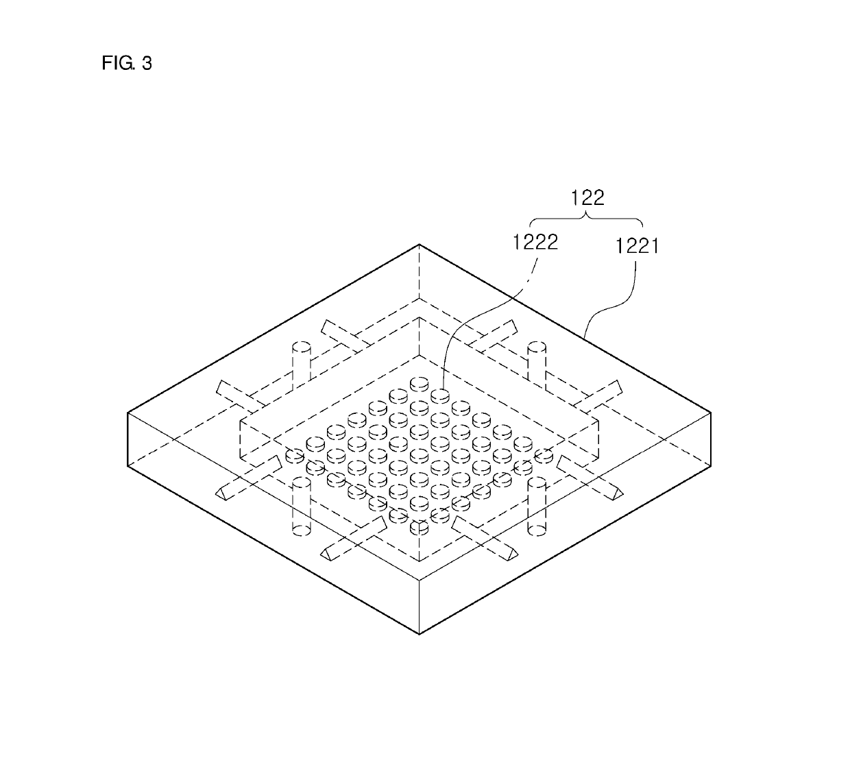
[0041]In the shape compliant gripper 100 according to the first embodiment of the present disclosure, the shape compliant module 120 is disposed on the body 110. The shape compliant module 120 is a module capable of controlling its ri...
third embodiment
[0068]According to the present disclosure, the bellows 3232 may be connected to the air pressure adjusting part via the port 3231, and the control part 323 may control the pressure inside the bellows 3232 by introducing the air into the bellows 3232 or discharging the air inside the bellows 3232 to the outside using the air pressure adjusting part so that the magnet part 322 can be moved to a desired position.
[0069]As illustrated in FIG. 6A, in a state in which the bellows 3232 are contracted, the magnet part 322 is located adjacent to the magnetorheological elastomer 321, and as illustrated in FIG. 6B, when the air is introduced into the bellows 3232 via the port 3231, the bellows 3232 expand and the magnet part 322 is moved to a position at which the magnet part 322 is spaced apart from the magnetorheological elastomer 321. On the contrary, when the air inside the bellows 3232 is discharged to the outside through the port 3231 in a state in which the bellows 3232 are expanded, the...
fourth embodiment
[0072]FIGS. 7A and 7B are cross-sectional views of a shape compliant gripper according to the present disclosure.
[0073]A magnet part 422 of a shape compliant gripper 400 according to the fourth embodiment of the present disclosure may include a plurality of permanent magnets 4222, and the plurality of permanent magnets 4222 may be disposed on a housing 4221. In the present embodiment, the permanent magnets 4222 may be formed to have a shape of a rod that extends in a depth direction of the paper, i.e., a direction in which the permanent magnets 4222 penetrates through FIGS. 7A and 7B, and each of tubes 4232 may be disposed between the plurality of adjacent permanent magnets 4222.
[0074]According to the present embodiment, a control part 423 may control the volume of the tubes 4232 disposed between the plurality of permanent magnets 4222, thereby controlling a distance between a magnetorheological elastomer 421 and the magnet part 422. To this end, in the present embodiment, the tubes...
PUM
 Abstract
Description
Claims
Application Information
 - R&D
- Intellectual Property
- Life Sciences
- Materials
- Tech Scout
- Unparalleled Data Quality
- Higher Quality Content
- 60% Fewer Hallucinations
Browse by: Latest US Patents, China's latest patents, Technical Efficacy Thesaurus, Application Domain, Technology Topic, Popular Technical Reports.
© 2025 PatSnap. All rights reserved.Legal|Privacy policy|Modern Slavery Act Transparency Statement|Sitemap|About US| Contact US: help@patsnap.com


