Device for pneumatically adjusting a seat in a transport means, in particular a motor vehicle

a technology for transportation means and seats, applied in the direction of movable seats, vehicle components, vehicle arrangements, etc., can solve the problems of large structural space requirements, high noise emissions and high costs, and the storage volume also requires a considerable amount of structural space, so as to achieve a small structural space, simple and fast seat adjustment, and low operating power

Active Publication Date: 2019-05-14
CONTI TEMIC MICROELECTRONIC GMBH
View PDF29 Cites 5 Cited by
  • Summary
  • Abstract
  • Description
  • Claims
  • Application Information

AI Technical Summary

Benefits of technology

[0006]An aspect of the invention provides an apparatus for the pneumatic adjustment of a seat in a transportation means, and in particular in a motor vehicle, which apparatus permits a simple and fast adjustment of the seat, with the apparatus simultaneously taking up a small structural space and having a low level of operating power.
[0009]An aspect of the invention has the advantage that, by way of the mechanical preload of the pneumatic actuating device, a fast adjustment of the seat during the transfer from the standby state into the activated state can be achieved, without the need for a pressure generator with high power and large structural space requirement to be provided for this purpose. Rather, an adequate mechanical preload can be built up already in preparatory fashion using pressure generators of low power, which preload is then available, in the activated state, for the fast adjustment of the seat.
[0012]In a further embodiment, the pneumatic actuating device in at least one adjustment device is designed such that, in the activated state, said pneumatic actuating device effects the movement of a movable flap which preferably forms a part of the seat contour, wherein the flap is held in a static position when the pneumatic actuating device is in the standby state. The flap is preferably articulatedly connected to a structure in the seat. In this variant of the invention, a conversion of the released preload into the mechanical movement of a flap is effected in a simple manner. In a preferred variant, the flap extends, at one side of the backrest of the seat, in the longitudinal direction of the backrest, in order thereby to provide a person situated in the seat with suitable lateral support.
[0015]In a further preferred embodiment, the first air bladder is connected to a compressed-air supply by way of a valve arrangement composed of one or more valves, in such a way that, by way of the control of the valve arrangement, filling of the first air bladder by way of the compressed-air supply for the purposes of establishing the standby state, and an evacuation of the air bladder after the ending of the activated state, are achieved, wherein automatic arresting of the flap is preferably effected upon the evacuation of the first air bladder. With this variant of the invention, a mechanism of simple construction is provided for the movement of the flap and thus for the seat adjustment.
[0021]It is preferably the case that, when the pneumatic actuating device according to the invention is in the activated state, pressure equalization takes place between the pneumatic actuating device (in particular a pneumatic stroke element) and the surroundings. Said pressure equalization does not require the involvement of a compressor, and can thus also take place considerably more quickly than the filling of an actuator by way of a small compressor.

Problems solved by technology

To achieve a fast adjustment time of a pneumatic seat adjustment, a very powerful pneumatic pressure supply is required, which in turn leads to a large structural space requirement, high noise emissions and high costs.
However, said storage volume also requires a considerable amount of structural space.

Method used


Image

  • Device for pneumatically adjusting a seat in a transport means, in particular a motor vehicle
  • Device for pneumatically adjusting a seat in a transport means, in particular a motor vehicle
  • Device for pneumatically adjusting a seat in a transport means, in particular a motor vehicle

Examples


second embodiment

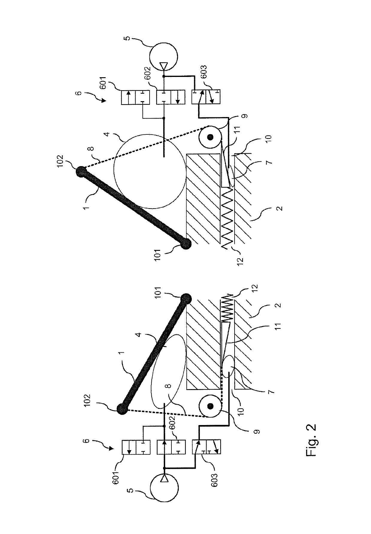
[0042]FIG. 2 shows an adjustment device according to an aspect of the invention, which, by contrast to the embodiment of FIG. 1, effects arresting of the flap 1 by way of frictional locking, and which furthermore permits a movement of the flap into various intermediate or end positions. In this way, a variable seat adjustment is made possible, such that the flap is for example moved to a lesser extent in the presence of low lateral accelerations than in the presence of relatively high lateral accelerations.

[0043]In the embodiment of FIG. 2, analogously to FIG. 1, a first air bladder 4 and a second air bladder 7 are provided, which are fed with compressed air from the compressor 5 via a valve device 6 composed of three valves 601 to 603. The valves 601 and 602 in this case correspond to the 2 / 2 valves of FIG. 1. However, by contrast to FIG. 1, the valve 603 of FIG. 2 is a 3 / 2 valve with three ports and two switching positions, wherein the first switching position connects the compres...

third embodiment

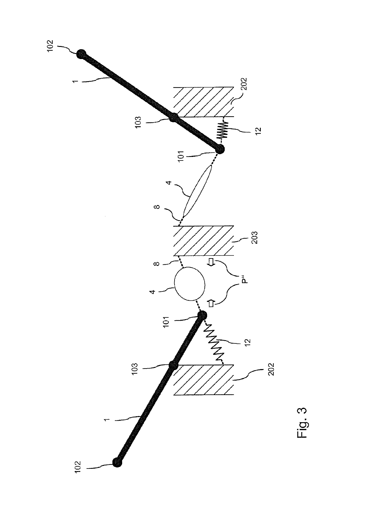
[0049]FIG. 3 shows an adjustment device according to an aspect of the invention. In this variant, the flap 1 is articulatedly connected to a structure 202 in the seat by way of a joint 103, such that a lever is produced by way of the flap. Between the end 101 of the flap and the structure 202, there is arranged a tension spring 12. Furthermore, the end 101 of the flap is connected by way of a cable 8 (indicated by way of a dashed line) and interposed air bladder 4 to a further structure 203 in the driver's seat. In the standby state in the left-hand part of FIG. 3, the tension spring 12 is stressed, which is effected by virtue of the air bladder 4 being filled. Said filling causes a shortening of the length of the air bladder 4 in the direction of the arrows P″, and thus to stretching of the spring 12, such that the latter generates a restoring force. In this way, in turn, a preload of the actuating device is realized in the standby position.

[0050]By way of a triggering device, whic...


PUM


Abstract

A device for pneumatically adjusting a seat in a transport vehicle, in particular in a motor vehicle, including one or more adjusting devices, each of which includes a pneumatic actuating device for adjusting the seat by generating pneumatic pressure, and including a trigger device, which the actuating device is switched from a standby state to an active state in response to a trigger signal when the device is being operated. The pneumatic actuating device brings about an adjustment of the seat in the active state. The pneumatic actuating device is designed such that the actuating device is mechanically preloaded in the standby state, and the mechanical preload is released in the active state in order to thus bring about the adjustment of the seat.

Description

CROSS REFERENCE TO RELATED APPLICATIONS[0001]This application is the U.S. National Phase Application of PCT International Application No. PCT / EP2015 / 051162, filed Jan. 21, 2015, which claims priority to German Patent Application No. 10 2014 201 663.0, filed Jan. 30, 2014, the contents of such applications being incorporated by reference herein.FIELD OF THE INVENTION[0002]The invention relates to an apparatus for the pneumatic adjustment of a seat in a transportation means, in particular in a motor vehicle.BACKGROUND OF THE INVENTION[0003]In transportation means, and in particular in motor vehicles, increasing use is being made of pneumatically actuated adjustment devices by way of which the position and in particular the contour of a seat can be suitably adapted. Inter alia, dynamic seat adjustment means are known which make it possible for the seat user to be supported in a manner dependent on the driving situation, for example during cornering maneuvers or in the presence of later...

Claims


Application Information

Patent Timeline
Patent Type & Authority Patents(United States)
IPC IPC(8): B60N2/02B60N2/18B60N2/16B60N2/427B60N2/22B60N2/90
CPCB60N2/0244B60N2/0224B60N2/0284B60N2/1665B60N2/1878B60N2/42763B60N2/914B60N2/99B60N2/22B60N2002/0268B60N2002/026B60N2002/0256B60N2/026B60N2/0256B60N2/0268
Inventor BEUSCHEL, MICHAELCINI, MEHMETRIEPL, JOHANN
Owner CONTI TEMIC MICROELECTRONIC GMBH
Why Eureka
Try Eureka