Method and system for fault detection and faulted line identification in power systems using synchrophasors-based real-time state estimation

Active Publication Date: 2019-05-14
ECOLE POLYTECHNIQUE FEDERALE DE LAUSANNE (EPFL)
View PDF4 Cites 0 Cited by
  • Summary
  • Abstract
  • Description
  • Claims
  • Application Information

AI Technical Summary

Problems solved by technology

Traditionally, fault detection together with the associated relaying schemes and fault location functionalities have been considered as separate processes since the latter usually requires computational efforts that do not fit the time latencies needed by the protections.
(1) Methods based on the fundamental frequency components of voltage and current signals, and
(2) Methods exploiting the characteristics of the fault-generated traveling waves. However, despite all the advancements in the field of fault location methods and systems for power grids, further improvements and solutions are necessary and required.

Method used


Image

  • Method and system for fault detection and faulted line identification in power systems using synchrophasors-based real-time state estimation
  • Method and system for fault detection and faulted line identification in power systems using synchrophasors-based real-time state estimation
  • Method and system for fault detection and faulted line identification in power systems using synchrophasors-based real-time state estimation

Examples


case 2

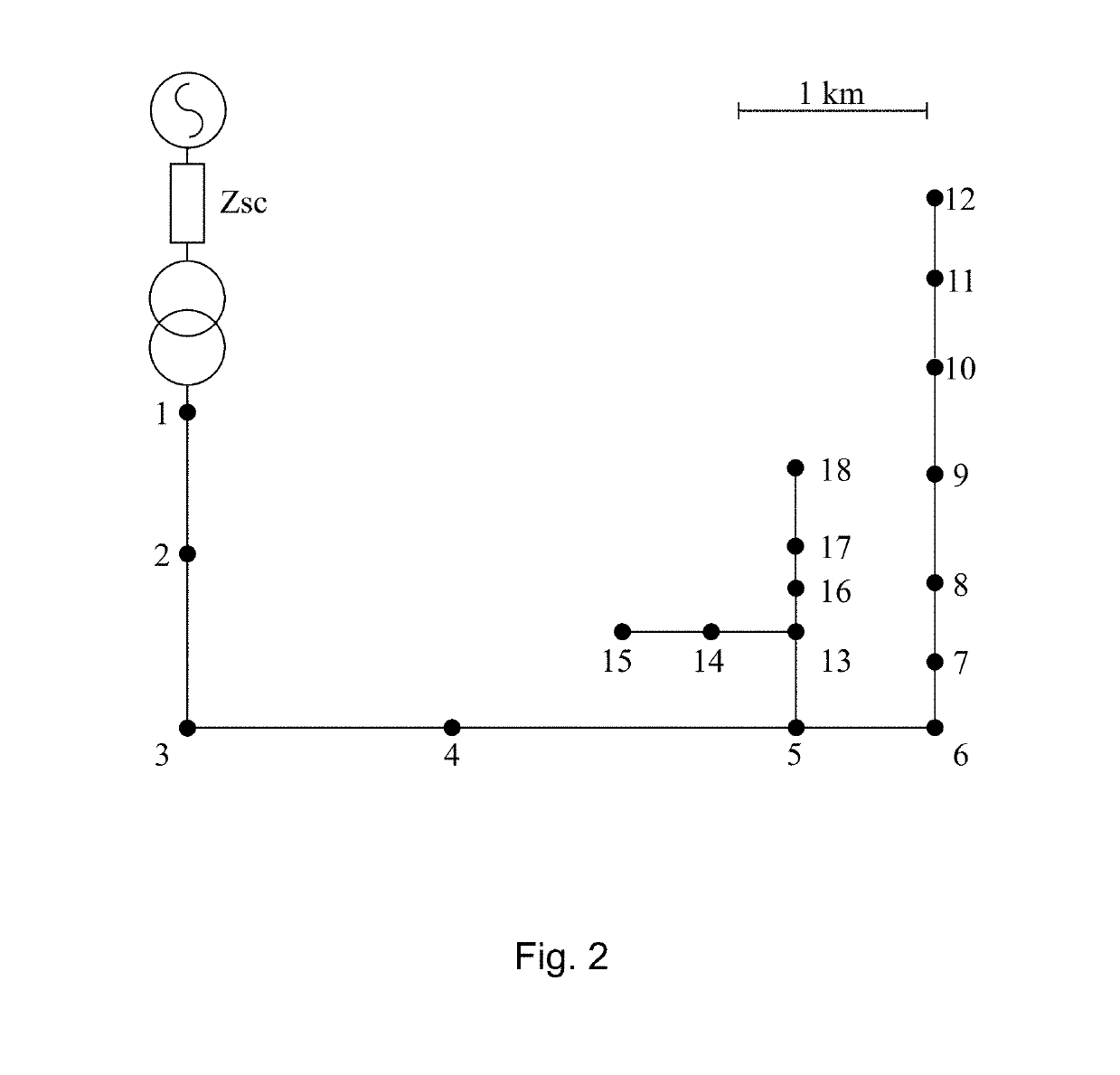
[0109]The performance of the method has been also assessed when dealing with faults in networks characterized by a large penetration of DG. The loads in bus #4, #10 and #17 have been coupled with variable pitch wind turbine models driving 160 kW squirrel cage asynchronous generators running at nominal speed. The power requested by the loads has been varied in order to create three different scenarios.[0110]Case 1: a passive network where the loads absorb approximately ¼ of the rated power of the real secondary substation transformers and the DG does not cover the load demand.[0111] an intermediate scenario where the loads absorb 50% of the power of Case 1, but the network is still passive.[0112]Case 3: the loads absorb 10% of the power of Case 1 so that the DG production is abundantly larger than the load demand making the feeder exporting power towards the upstream grid. For these tests, we have used the case characterized by the worst accuracy performance, namely a high impedance ...


PUM


Abstract

A method for a faulted line identification in a power network, including, at a generic time-instant, solving a plurality of parallel phasor measurement units based real-time state estimators, the state estimators having among each other different and augmented network topologies, each of the augmented network topologies comprises an original network topology, which includes a plurality of real buses and real lines forming a connected graph mapping the real network topology, and a single additional virtual bus located along one of the real lines, the line in which the virtual bus is located has to be different for each of the augmented network topologies.

Description

TECHNICAL FIELD[0001]The present invention relates to the field of power system, and more particularly is related to a system and a method for fault detection and faulted line identification in a network of a power system.DISCUSSION OF THE BACKGROUND[0002]The massive integration of distributed generation (DG) of power is leading to important changes in the operation of distribution networks. In this context, the protection schemes are experiencing major transformations. Traditionally, fault detection together with the associated relaying schemes and fault location functionalities have been considered as separate processes since the latter usually requires computational efforts that do not fit the time latencies needed by the protections. Along the years, several fault detection and location methods have been proposed for distribution networks. The majority of them are based on impedance measurements, traveling waves or phasor measurements. However, the literature only discusses the ...

Claims


Application Information

Patent Timeline
Patent Type & Authority Patents(United States)
IPC IPC(8): G01R31/08G01R19/25
CPCG01R31/088G01R31/086Y04S10/522Y02E60/728Y04S10/265G01R19/2513Y02E40/70Y02E60/00Y04S10/00Y04S10/22Y04S10/52
Inventor PIGNATI, MARCOZANNI, LORENZOROMANO, PAOLOPAOLONE, MARIO
Owner ECOLE POLYTECHNIQUE FEDERALE DE LAUSANNE (EPFL)
Why Eureka
Try Eureka