

Terminal fitting and connector
a technology of fittings and connectors, applied in the direction of coupling contact members, coupling device connections, electrical devices, etc., can solve the problems of inability to utilize the configuration of japanese unexamined patent publication no. 2002-274290 in the case of large current applications, and the bent part is difficult to resiliently deform, so as to increase the thickness of the plate
- Summary
- Abstract
- Description
- Claims
- Application Information
AI Technical Summary
Benefits of technology
Problems solved by technology
Method used
Image

Examples
Embodiment Construction
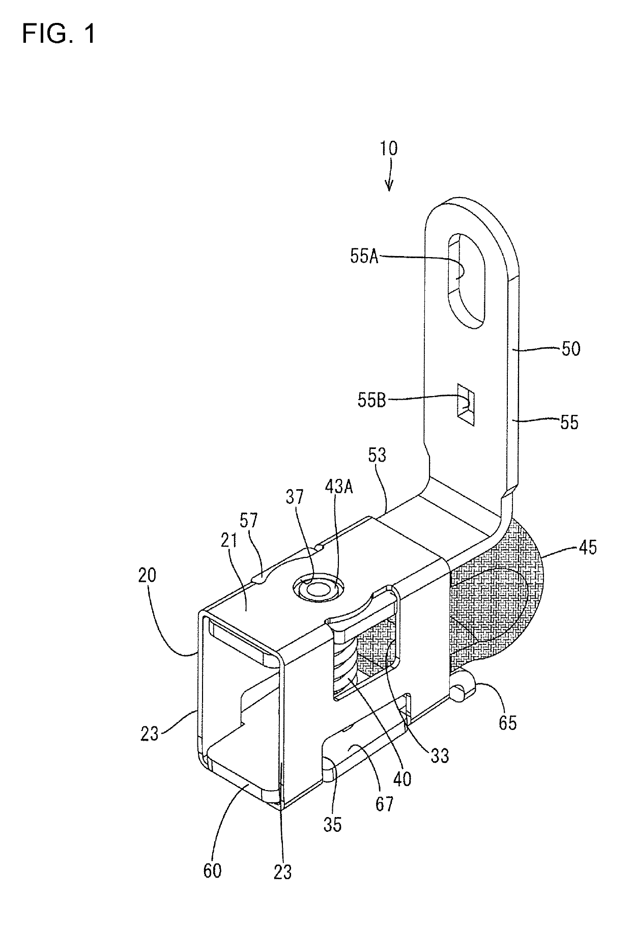
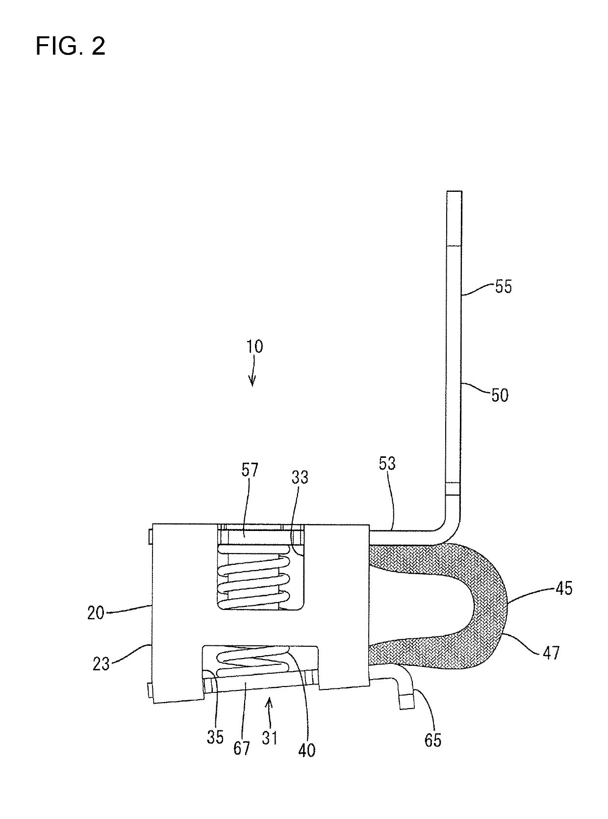
[0024]An embodiment is described with reference to FIGS. 1 to 10. A terminal fitting 10 of this embodiment is connected electrically to a mating terminal 90 by being butted against the mating terminal 90. In the following description, an upper side in FIG. 2 and a lower side (side of the mating terminal 90) in FIG. 2 are referred to as an upper side and a lower side. Further, a left side in FIG. 2 and a right side (side of a braided wire 45) in FIG. 2 are referred to as a front and a rear.
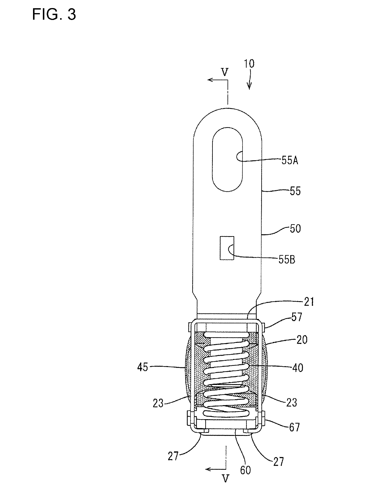
[0025]The terminal fitting 10 includes, as shown in FIG. 1, a case 20, a coil spring 40 (example of a “resilient member”) accommodated in a compressed state inside the case 20, an intermediate terminal 50 disposed above the coil spring 40, an electrical contact 60 disposed below the coil spring 40 and the braided wire 45 conductively connecting the intermediate terminal 50 and the electrical contact 60.
[0026]The case 20 is formed by press-working a metal plate material such as a SUS material and in...
PUM
 Abstract
Description
Claims
Application Information