
Medical imaging system and operation method therefor

a medical imaging and imaging system technology, applied in the field of medical imaging systems, can solve the problems of not being able to easily identify a facial change after treatment, the use of only x-ray radiographs cannot meet the demand, and the cost of 3d imaging devices is high, so as to reduce the cost and time of generating the 3d surface image, improve the effect of efficiency and reduce the inconvenience of the examin

Active Publication Date: 2019-06-04
VA TECHNOLOGIE +1
View PDF22 Cites 4 Cited by
  • Summary
  • Abstract
  • Description
  • Claims
  • Application Information

AI Technical Summary

Benefits of technology

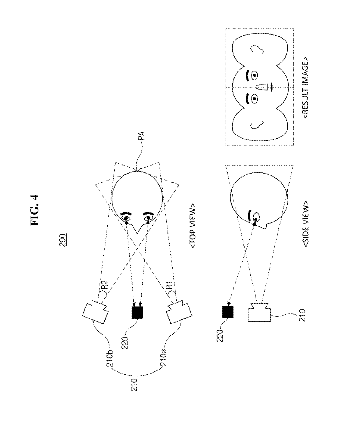
The present invention is about a method to capture a 3D surface image using a conventional camera and a 3D X-ray image. This allows for a 3D surface image to be obtained without using a separate device, reducing costs and time. Additionally, a vision drawing means can be used to fix the examinee's vision, improving the accuracy and reliability of the 3D surface image and reducing the examinee's psychological discomfort. A vision sensing means can also be used to improve the accuracy and reliability of the 3D surface image, and improve the system's convenience for use.

Problems solved by technology

However, since the X-ray radiograph illustrates an inside of a human body, an ordinary person is not accustomed to the X-ray radiograph except for a trained professional such as a doctor.
Especially, in the dental or plastic surgery field, use of only the X-ray radiograph cannot satisfy demand for easily identifying a facial change after treatment.
However, it is problematic in that the 3D imaging device is very expensive, and takes much time for 3D scanning.

Method used


Image

  • Medical imaging system and operation method therefor
  • Medical imaging system and operation method therefor
  • Medical imaging system and operation method therefor

Examples


first embodiment

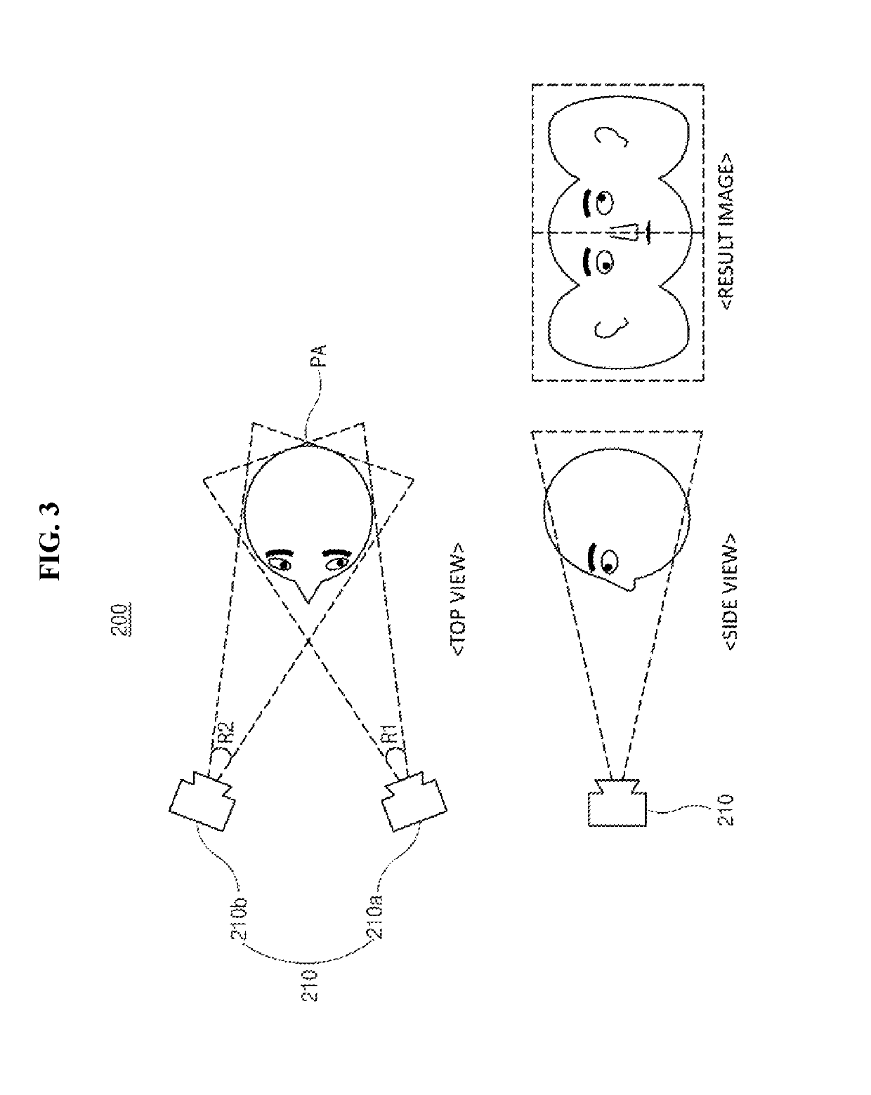
[0027]The medical imaging system 10 according to the present invention is configured to form a 3D surface image by synthesizing 2D surface images with a 3D X-ray radiograph. For convenience, in the embodiments of the present invention, the medical imaging system for generating a facial image is described.

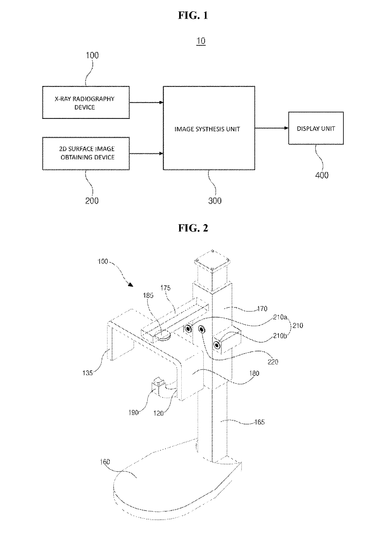
[0028]Referring to FIG. 1, the medical imaging system 10 according to the embodiments of the present invention may include the X-ray radiography device 100, the 2D surface image obtaining device 200, an image synthesis unit 300, and a display unit 400.

[0029]The X-ray radiography device 100 is configured to obtain a 3D X-ray radiograph of an examinee PA, for example, an 3D X-ray radiograph of the examinee's head. As an example, a device for dental computed tomography (CT) may be utilized, but not limited thereto.

[0030]The X-ray radiography device 100 is described with reference to FIG. 2. The X-ray radiography device 100 may include: a base 160 by which the X-ray radiography device 1...

second embodiment

[0062]FIG. 5 is a schematic view illustrating a 2D surface image obtaining device of a medical imaging system according to the present invention.

[0063]For convenience, detailed descriptions of the same configuration as or similar configuration to the medical imaging system according to the first embodiment are omitted.

[0064]Referring to FIG. 5, the 2D image obtaining device 200 according to the second embodiment of the present invention may include a vision sensing means 230.

[0065]The vision sensing means 230 may include an eye tracking device for tracking positions of the examinee's pupils. The eye tracking device may be configured as a video analysis method of detecting movements of the examinee's pupils by analyzing a real-time video image so as to calculate a direction of the examinee's line of vision based on a fixed position reflected in the examinee's corneas, a contact lens method of using a light reflected in a contact lens including a mirror or using a magnetic field of a ...


PUM


Abstract

The purpose of the present invention is to provide a method for obtaining a more effective 3D facial image for medical use. The present invention provides a medical imaging system includes a 2D surface image obtaining device including at least one camera for photographing a plurality of 2D facial images of an examinee, at different photography angles or ranges, a visual guidance configured to fix an examinee's line of vision, an X-ray radiography device for radiographing a 3D X-ray radiograph of the examinee's head, and an image synthesis unit for generating a 3D facial image by matching the plurality of 2D facial images with the 3D X-ray radiograph.

Description

CROSS REFERENCE TO RELATED APPLICATIONS[0001]This application is a National Stage Patent Application of PCT International Patent Application No. PCT / KR2015 / 002384 (filed on Mar. 12, 2015) under 35 U.S.C. § 371, which claims priority to Korean Patent Application No. 10-2014-0029120 (filed on Mar. 12, 2014), the teachings of which are incorporated herein in their entireties by reference.TECHNICAL FIELD[0002]The present invention relates generally to a medical imaging system. More particularly, the present invention relates to a medical imaging system capable of efficiently obtaining a medical 3D facial image and an operation method therefor.BACKGROUND ART[0003]In general, in the medical field, an X-ray radiograph, such as computed tomography (CT), is used for a diagnosis.[0004]However, since the X-ray radiograph illustrates an inside of a human body, an ordinary person is not accustomed to the X-ray radiograph except for a trained professional such as a doctor.[0005]Especially, in the...

Claims


Application Information

Patent Timeline
Patent Type & Authority Patents(United States)
IPC IPC(8): A61B6/00A61B6/10A61B6/14A61B3/113A61B3/00A61B5/00A61B6/03A61B6/51
CPCA61B6/4417A61B3/0091A61B3/113A61B5/0077A61B6/5247A61B6/10A61B6/14A61B6/4429A61B6/501A61B6/032A61B6/51
Inventor LIM, HYUNG KEUNCHUN, JIN PYO
Owner VA TECHNOLOGIE
Learn More