Control unit for hydraulic variable displacement pumps and variable displacement pump with a control unit

a control unit and variable displacement technology, applied in the direction of pump control, positive displacement liquid engine, thin material handling, etc., can solve the problem of requiring a large number of components, and achieve the effect of increasing the deflection of the variable displacement pump, reducing the force, and creating flexibility

Active Publication Date: 2019-06-04
DANFOSS POWER SOLUTIONS AS
View PDF7 Cites 2 Cited by
  • Summary
  • Abstract
  • Description
  • Claims
  • Application Information

AI Technical Summary

Benefits of technology

[0008]In this way, the mounting of the control piston by means of the two springs enables output levels to be set via the actuator which are automatically controlled in a load-dependent manner by the high pressure of the variable displacement pump. For example, if the first spring on the high-pressure / inlet side of the control piston together with the high pressure generates a greater force than the second spring on the outlet side of the control piston, and the actuator is set to zero power, the control piston is moved into a position of maximum deflection on the outlet side which corresponds to the minimum output of the variable displacement pump. In this position, a hydraulic connection between the high pressure inlet and the servo control device is opened to maximum extent.
[0016]In the case of the preferred embodiment of the controlled reduction of hydraulic pressure or displacement volume, the variable displacement pump is logically set to its starting position, i.e. when the actuator is inactive, such that it generates minimum supply pressure. To this end, the control piston must be positioned in fully deflected position on the outlet side of the housing so that the cross-section for the hydraulic link between the high pressure input and the servo connection is opened to maximum extent by the relevant control edge. In this starting position, the control piston is moved into a maximum position on the outlet side by the spring force of the spring on the inlet side as well as by the hydraulic pressure of the variable displacement pump acting against the spring, and it is held in place in this position. In this way, the maximum possible pressure acts on the servo piston, which therefore returns the adjustment element on the variable displacement pump to maximum extent in the direction of zero displacement volume. Also logically, an actuator force must now be applied such that the control piston is moved from its position of maximum deflection from the outlet side of the control housing in the direction of the inlet side. This can be effected by means of an actuator on the inlet side, if this is capable of exerting a tractive force on the control piston, or else by means of an actuator on the outlet side of the control housing if this exerts a compressive force on the control piston. When the control piston is pushed towards the inlet side, the cross-section of the opening for the connection of the line to the servo control device becomes successively smaller, thereby reducing the force that can be exerted by the servo piston on the adjustment element of the variable displacement pump and increasing the deflection of the variable displacement pump as is inherent to its design, i.e. increasing its displacement volume / supply pressure. As the actuator force increases in this preferred embodiment, the supply pressure of the hydraulic pump likewise increases, preferably proportionally to the actuator force.
[0017]The control device for single-sided variable displacement pumps according to the invention thereby provides for a flexible position of the actuator, which can be placed on the side adjacent to either the inlet or the outlet of the control piston. Only the direction of the actuator force has to be taken into account so that the force generated by the actuator results in the control piston being shifted in the direction of the first or second side of the control device. This variable positioning creates flexibility in allowing for installation space specifications in a work machine, for example. At the end of the control housing opposite the actuator it is also preferable to provide an adjustment device for the spring positioned there, preferably in the form of a setting screw. Adjustment of the adjustable spring is preferably carried out in an axial direction of the spring using a setting screw that acts on one end of the spring and that is mounted in a thread located in the housing of the control piston. The adjustment device for the spring at the opposite end from the actuator allows simple, precise, effective and reliable adjustment of the starting position, also making it possible to specify the minimum force of the actuator at which the actuator force causes the control piston to shift in the control casing.
[0019]Another preferred embodiment of the invention is such that that both the first spring on the inlet side and the second spring on the outlet side are each placed adjacently in a spring chamber but outside the pressure chambers in the control housing. Furthermore, it is preferable for the two spring chambers to be connected via a through-hole so that when the control piston is shifted, pressure equalization can occur between the two spring chambers via the through-hole. In addition, one of the two spring chambers can be connected to the outlet line to the tank by means of a connection line in the housing so that this line can also bring about further pressure equalization between the spring chambers at tank pressure level. The tank pressure level can, for example, be the housing pressure level if the pressure fluid reservoir which feeds the variable displacement pump constitutes a volume integrated in the housing of the variable displacement pump.

Problems solved by technology

A disadvantage in the control device shown in DE 199 49 169 A1 is that it requires a large number of components and an additional, elaborate pressure control valve placed between the outlet to the tank and the housing of the control piston, and that the control piston and servo piston interact via a spring.

Method used


Image

  • Control unit for hydraulic variable displacement pumps and variable displacement pump with a control unit
  • Control unit for hydraulic variable displacement pumps and variable displacement pump with a control unit
  • Control unit for hydraulic variable displacement pumps and variable displacement pump with a control unit

Examples


Embodiment Construction

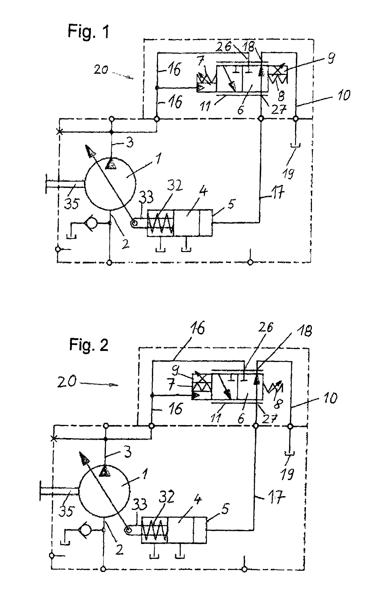
[0029]FIG. 1 shows a variable displacement pump 1 with a control device 20 according to the invention in diagrammatic form. The type of the variable displacement pump 1 is optional, providing that the adjustment of the displacement volume can be controlled by means of an adjustment element that can be activated by a servo piston 4.

[0030]Preferred examples here are axial piston pumps with an adjustable swash plate whose angular position can be specified by means of a servo piston 4. The variable displacement pump 1 is powered by a drive shaft 35 with a drive motor not shown here operating at a constant rotational speed, for example, and it displaces pressure fluid in an open circuit. The variable displacement pump comprises and inlet 2 and an outlet 3 for the pressure fluid and is connected to a consumer not shown here via pressure lines, as well as being connected to the control device 20 via a pressure line 16 and to a tank 19 for the pressure fluid via a drain line 10.

[0031]The co...


PUM


Abstract

Control device for hydraulic variable displacement pumps operated in an open hydraulic circuit and adjustable in their displacement volume by means of a servo control device. The control device comprises a control piston with two control edges to which pressure can be applied by means of pressurized pressure fluid from a variable displacement pump, the control piston being mounted in a housing so that it shifts longitudinally. The housing of the control piston comprises an inlet for the connection of a high pressure line of a variable displacement pump, an outlet which can be connected to a tank and a servo connection which can be linked to a servo cylinder, whereby a link between the inlet and the servo connection can be made via a first control edge. It is possible to create a link between the servo connection and the outlet via a second control edge.

Description

BACKGROUND OF THE INVENTION[0001]The invention concerns a control device for hydraulic variable displacement pumps which are adjustable on one side according to the generic concept of claim 1 and a variable displacement pump fitted with such a control device according to claim 10. In particular, the invention concerns hydraulic variable displacement pumps which are operated in an open hydraulic circuit and which are adjustable by means of a servo piston that can shift inside a servo cylinder, to which, in turn, pressure can be applied via a control device by means of pressurized pressure fluid. For this purpose, the servo piston acts on a displaceable adjustment element or transmission component, for example the swash plate or the bent axis, thereby adjusting the angular position of the latter and thus also the displacement volume of the variable displacement pump according to the position of the control piston in the control device. The variable displacement pump is preferably conf...

Claims


Application Information

Patent Timeline
Patent Type & Authority Patents(United States)
IPC IPC(8): F04B1/32F04B49/00F04B49/08F04B49/12
CPCF04B49/08F04B1/324F04B49/12F04B49/002Y10T137/86622
Inventor ZAVADINKA, PETERSMOLKA, STANISLOVSEDO, PAVOL
Owner DANFOSS POWER SOLUTIONS AS
Why Eureka
Try Eureka