Face mask having improved comfort through cooling of microclimate through use of a phase change material

a technology of phase change material and comfort layer, which is applied in the direction of breathing protection, protective equipment, protective garments, etc., can solve the problems of increasing the cost of the structure, increasing the weight of the structure, and reducing the porosity of the structur

Active Publication Date: 2019-06-11
OWENS & MINOR INC +3
View PDF28 Cites 8 Cited by
  • Summary
  • Abstract
  • Description
  • Claims
  • Application Information

AI Technical Summary

Benefits of technology

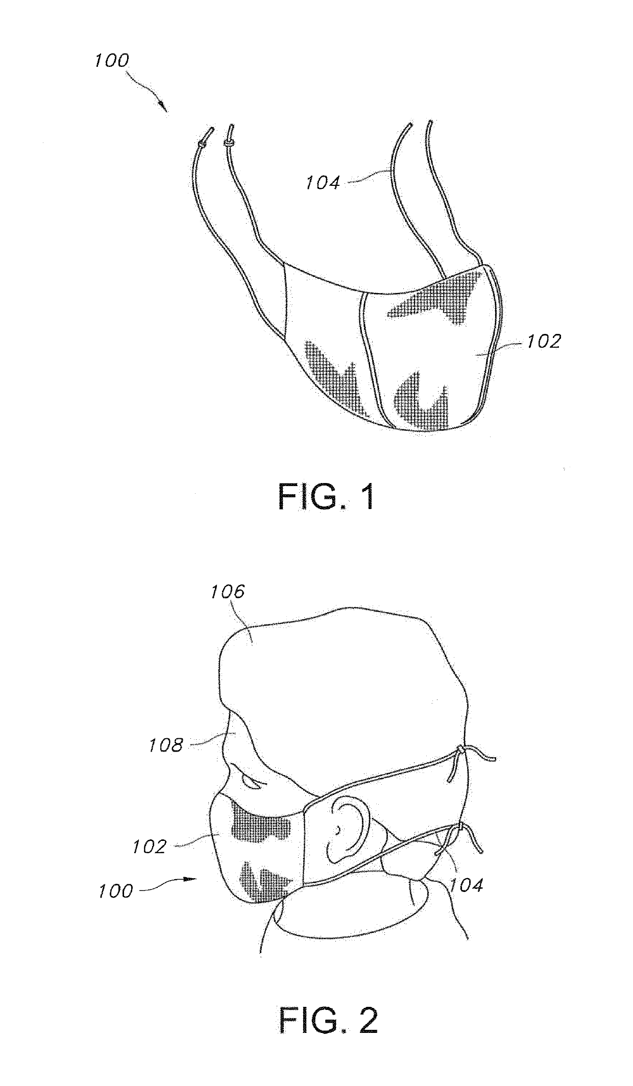
[0014]In yet another embodiment, the face mask can cool a microclimate formed between the inner layer of the face mask and a wearer's face by a temperature ranging from about 1° C. to about 7° C. after exhalation by the wearer.
[0025]In an additional embodiment, the inner layer of material, the outer layer of material, or a combination thereof can include a thermally conductive material, wherein the thermally conductive material reduces the R-value of the inner layer of material, the outer layer of material, or a combination thereof.
[0026]In another embodiment, a coating comprising a thermally conductive material can be disposed on a surface of the inner layer of material, a surface of the outer layer of material, or a combination thereof, wherein the thermally conductive material reduces the R-value of the inner layer of material, the outer layer of material, or a combination thereof.
[0028]In one more embodiment, the inner layer of material, the outer layer of material, or a combination thereof can include a moisture absorptive material, wherein the moisture absorptive material reduces the R-value of the inner layer of material, the outer layer of material, or a combination thereof. In addition, the moisture absorptive material can include cotton fibers, rayon fibers, surfactant-treated cellulosic fibers, or a combination thereof.

Problems solved by technology

However, these solutions may increase the cost of the structure, increase the weight of the structure, reduce the porosity of the structure, and add discomfort to the wearer by negatively impacting the thermal resistance of the multi-layered structure.
However, it is often the case that fluid will saturate this high loft material, hence reducing its effectiveness in absorbing the energy of a future fluid splash.
Moreover, incorporating additional layers of material into the mask can increase the amount of heat contained within the mask's microclimate, which can cause discomfort to the wearer.
Just a few degrees of heat can be very uncomfortable and result in the wearer feeling they mask is unbreathable and can prevent a person from not complying with PPE protocols.

Method used


Image

  • Face mask having improved comfort through cooling of microclimate through use of a phase change material
  • Face mask having improved comfort through cooling of microclimate through use of a phase change material
  • Face mask having improved comfort through cooling of microclimate through use of a phase change material

Examples


example 1

[0156]In Example 1, the temperature profiles for the microclimate inside the dead space of pleated face masks having a length of 17.5 centimeters and a width of 18.4 centimeters, where the inner-facing surface of the inner layer has a surface area of 0.032 m2 and incorporating various configurations of an encapsulated phase change material disposed on a nonwoven polyester substrate, were recorded via thermal imaging and compared to a control mask that did not include an encapsulated phase change material, and the results are shown in the time lapse images shown in FIGS. 15-17. Specifically, FIG. 15 illustrates a thermal imaging profile during inhaling (left) and exhaling (right) over a 45 minute period for a user wearing the control face mask of Example 1, where no phase change material is present on the inner-facing surface of the inner layer of the face mask; FIG. 16 illustrates a thermal imaging profile during inhaling (left) and exhaling (right) over a 45 minute period for a use...

example 2

[0161]In Example 2, the temperature profiles for the microclimate inside the dead space of several types of face masks incorporating various configurations of an encapsulated phase change material disposed on a nonwoven polyester substrate were recorded via thermal imaging and compared to a control mask that did not include an encapsulated phase change material, and the results are shown in the time lapse images shown in FIGS. 18-40. The pleated face masks tested in FIGS. 18-27, 30-34, and 36-40 have a length of 17.5 centimeters and a width of 18.4 centimeters, where the inner-facing surface of the inner layer has a surface area of about 0.032 m2, while the inner-facing surface of the inner layer of the mask tested in FIGS. 28 and 35 has a total surface area of about 0.023 m2, and the inner-facing surface of the inner layer of the mask tested in FIG. 29 has a total surface area of about 0.0305 m2. Further, when a 6 millimeter border was used, the surface area of the border was about...

example 3

[0195]In Example 3, a multi-layered structure generally corresponding to the arrangement shown in FIG. 9 (Control Sample) but without the three-dimensional spaces 302 was compared to a multi-layered structure arranged as shown in FIG. 9 (Test Sample) for their ability to achieve Level 3 performance, which is the most stringent level of testing in ASTM F2100-11, where a face mask must resist splashes of 2 milliliters of synthetic blood (available from Johnson, Moen & Co., 2505 Northridge Lane NE, Rochester, Minn. 55906) at 160 mmHg per the ASTM F1862-13 procedure. In other words, the control sample included the four-layered structure 860 except for the three-dimensional spacers 302. The control sample multi-layered structure had an outer layer of material 802 formed from a polyester pulp wetlaid material having a basis weight of 0.5 ounces per square yard (16.95 gsm) and having an outer-facing surface 810. The control sample multi-layered structure 860 also included an inner layer of...


PUM

PropertyMeasurementUnit
widthaaaaaaaaaa
temperatureaaaaaaaaaa
surface areaaaaaaaaaaa

Abstract

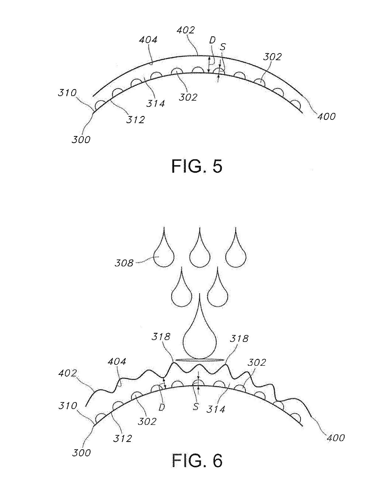
A multi-layered face mask coated with discontinuous patterns of phase change material are incorporated into the face mask construction to provide for cooling of the microclimate in the dead space of the face mask. Optimized cooling is achieved by strategic placement of layers coated with a phase change material within the mask construction and the amount and density of the phase change material in contact with the temperature sensitive areas of the face, as well as areas experiencing the maximum amount of flux from exhaled breath. The shape of the mask can also be adjusted to increase skin contact with the phase change material and decrease dead space volume, which reduces the volume of warm exhaled air and can provide sufficient cooling with less phase change material. The discontinuous patterns of phase change material also provide inter-layer spacing between the layers of the mask, which can improve splash resistance.

Description

RELATED APPLICATION[0001]The present application is the national phase of and claims priority to PCT / US2017 / 028481, filed Apr. 20, 2017, which claims priority to U.S. Provisional Application Ser. No. 62 / 325,729 filed on Apr. 21, 2016, both of which are incorporated herein in their entirety by reference thereto.BACKGROUND OF THE INVENTION[0002]The use of face masks and other personal protective equipment (PPE) such as surgical gowns, surgical drapes, bouffant caps, etc. is a recommended practice in the healthcare industry to help prevent the spread of disease. For instance, face masks worn by healthcare providers help reduce infections in patients by filtering the air exhaled from the wearer thus reducing the number of harmful organisms or other contaminants released into the environment.[0003]This is especially important during surgeries where the patient is much more susceptible to infection due to the presence of an open wound site. Similarly, patients with respiratory infections ...

Claims


Application Information

Patent Timeline
Patent Type & Authority Patents(United States)
IPC IPC(8): A62B18/08A41D13/005A41D13/11A62B18/02B32B3/30
CPCA41D13/0056A41D13/11B32B2571/00B32B2307/30B32B3/30A41D13/0053A41D31/125A41D31/305A41D13/1107A41D31/02
Inventor POTNIS, PRASAD S.NASH, CHRISTENA K.STEINDORF, ERIC C.HOUDE, AJAY Y.HURDLE, JOSEPH D.
Owner OWENS & MINOR INC
Why Eureka
Try Eureka