Piezoelectric vibrating strip, piezoelectric vibrator, oscillator, electronic device, and radio timepiece

a piezoelectric and vibrating arm technology, applied in piezoelectric/electrostrictive/magnetostrictive devices, piezoelectric/electrostriction/magnetostriction machines, piezoelectric/electrostrictive device details, etc., can solve the problem of difficult use of vibrating arm as various timing sources, and achieve the effect of reducing the r1 value and preventing the vibration of the vibrating arm portion

Inactive Publication Date: 2014-01-30
SII CRYSTAL TECH
View PDF3 Cites 3 Cited by
  • Summary
  • Abstract
  • Description
  • Claims
  • Application Information

AI Technical Summary

Benefits of technology

[0043]This configuration can provide the radio timepiece capable of preventing the vibration of the vibrating arm portion in the second warp mode while further reducing the R1 value.
[0044]According to the present invention, the piezoelectric vibrating strip, the piezoelectric vibrator, the oscillator, the electronic device, and the radio timepiece in which the R1 value can be reduced further while preventing the vibrating arm portion from vibrating in the second warp mode can be provided.

Problems solved by technology

In the harmonic mode, however, the vibrator generally vibrates at a frequency higher than a frequency typically required, and the vibrator is difficult to use as various timing sources.
The related art described above, however, has the following problems.

Method used


Image

  • Piezoelectric vibrating strip, piezoelectric vibrator, oscillator, electronic device, and radio timepiece
  • Piezoelectric vibrating strip, piezoelectric vibrator, oscillator, electronic device, and radio timepiece
  • Piezoelectric vibrating strip, piezoelectric vibrator, oscillator, electronic device, and radio timepiece

Examples


first embodiment

(Piezoelectric Vibrator)

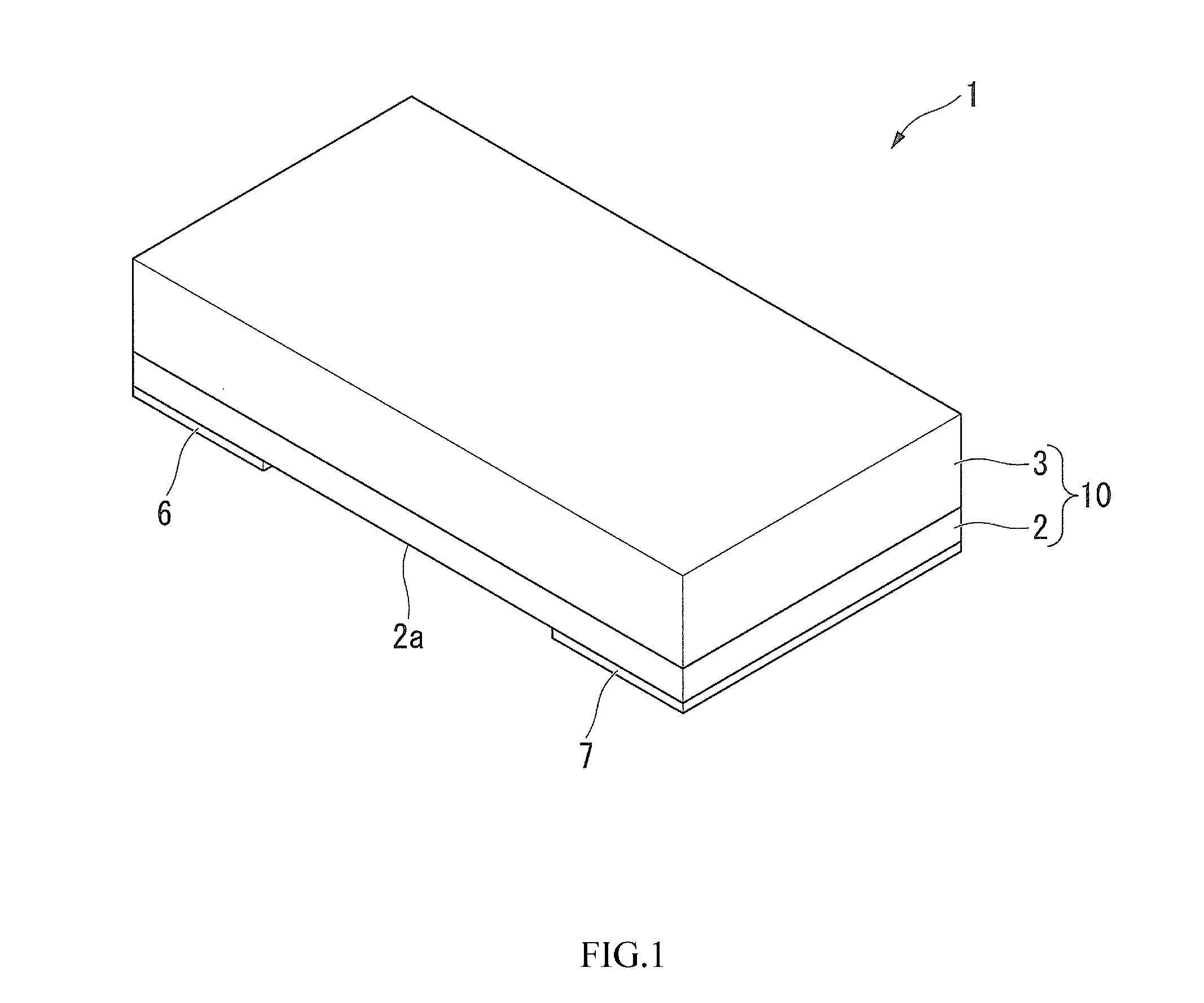
[0068]Next, a first embodiment of the present invention will be described with reference to FIG. 1 to FIG. 6.

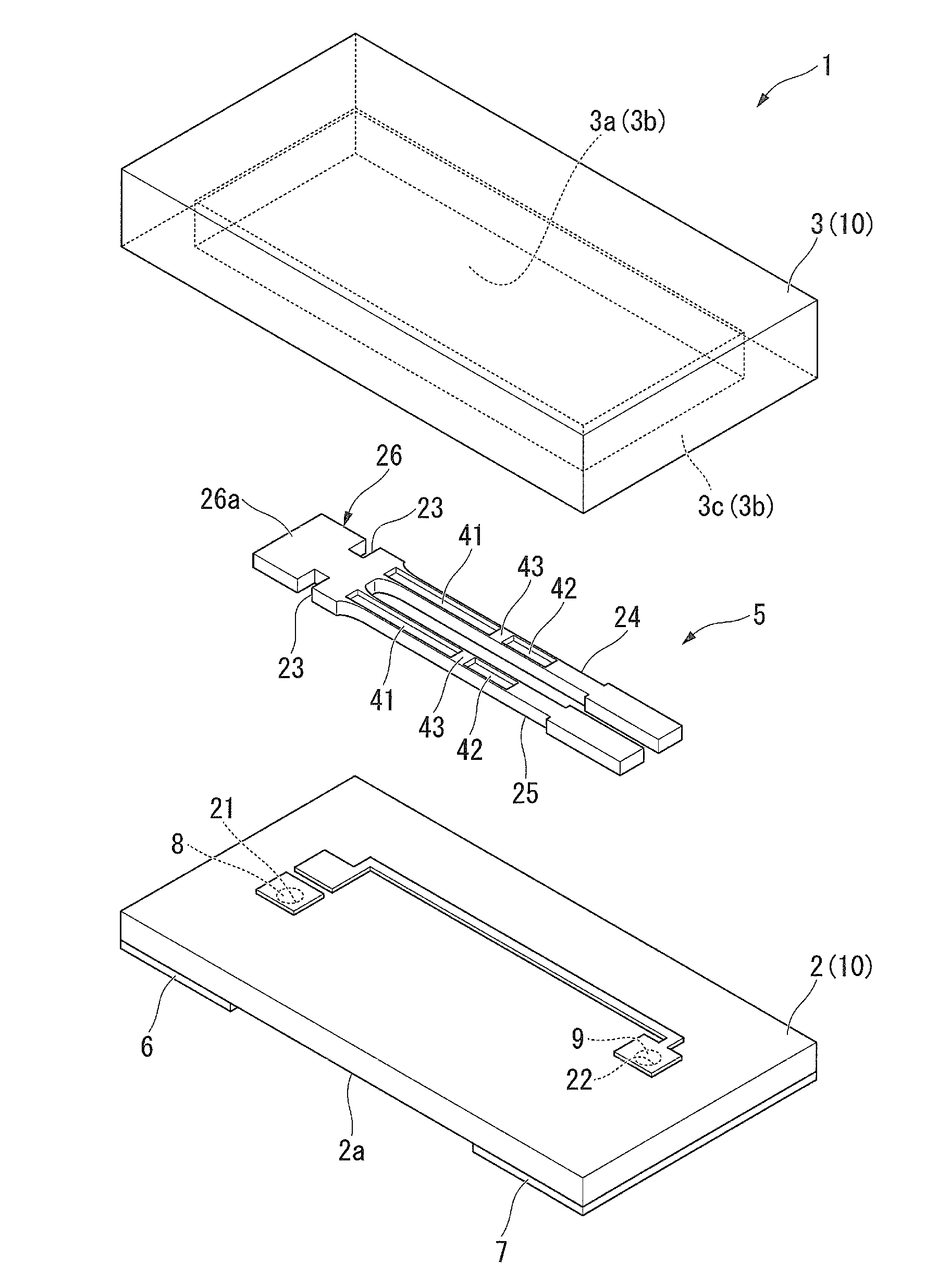
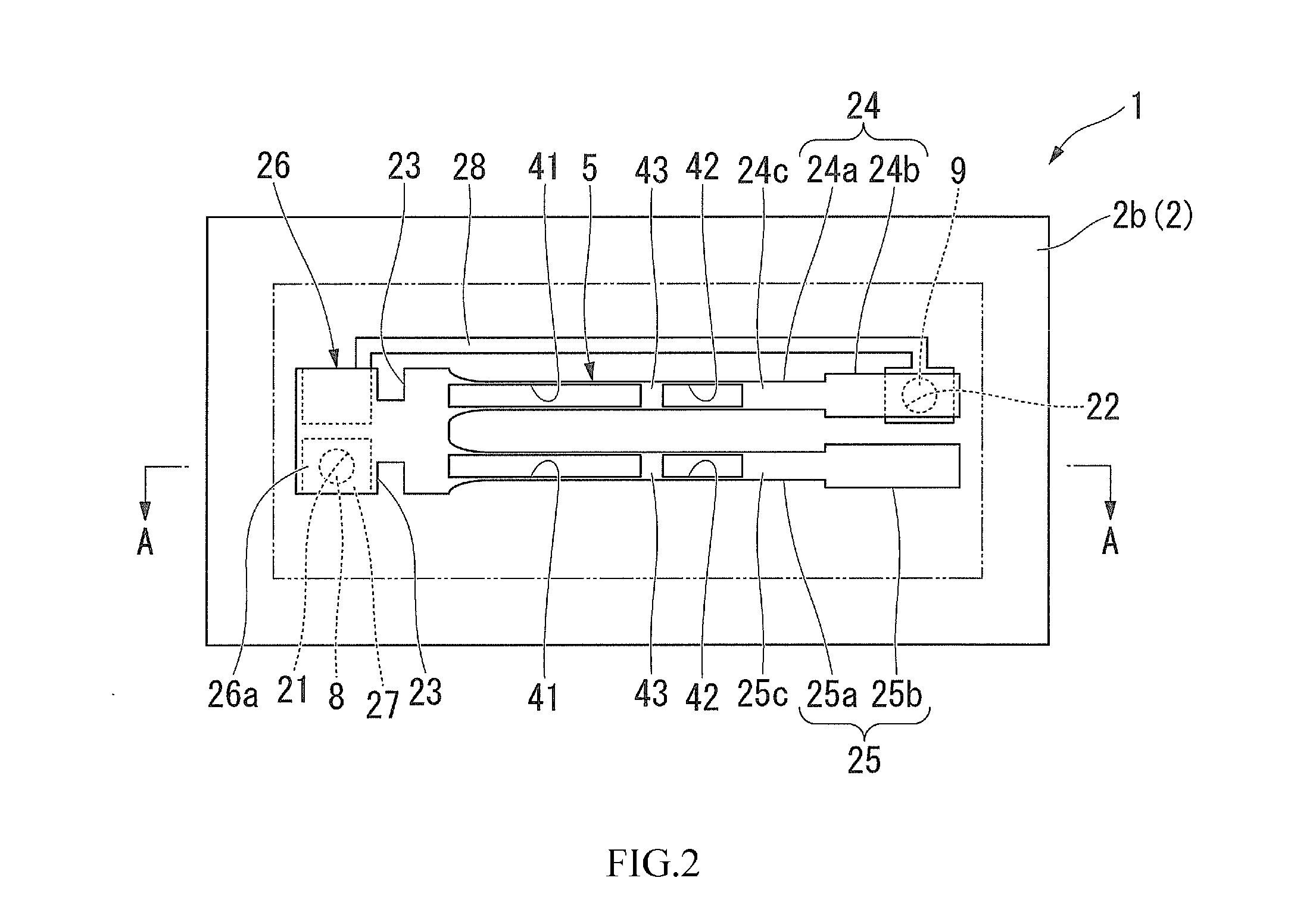
[0069]FIG. 1 is a perspective view showing the outer appearance of a piezoelectric vibrator in the present embodiment viewed from a lid substrate. FIG. 2 is a diagram of the internal structure of the piezoelectric vibrator and shows a piezoelectric vibrating strip viewed from above with the lid substrate removed therefrom. FIG. 3 is a section view taking along an A-A line in FIG. 2. FIG. 4 is an exploded perspective view of the piezoelectric vibrator.

[0070]As shown in FIG. 1 to FIG. 4, a piezoelectric vibrator 1 according to the present embodiment is of a surface-mounting type including a package 10 of box shape provided by anode-bonding a base substrate 2 to a lid substrate 3 with a bonding material, not shown, interposed between them, and a piezoelectric vibrating strip 5 housed in a cavity C of the package 10. The piezoelectric vibrating strip 5 is ...

second embodiment

[0103]Next, a second embodiment of the present invention will be described by using FIG. 1 and FIG. 3 again and with reference to FIG. 7 and FIG. 8. The same aspects as those in the first embodiment are described with the same reference numerals (this applies also to the other embodiments described below).

[0104]FIG. 7 is a plan view of a piezoelectric vibrating strip in the second embodiment.

[0105]The second embodiment is similar to the first embodiment described above in the basic configuration (this applies also to the other embodiments describe below) in which a piezoelectric vibrator 1 is of a surface mounting type including a package 10 of box shape provided by anode-bonding a base substrate 2 to a lid substrate 3 with a bonding material, not shown, interposed between them, and a piezoelectric vibrating strip 105 housed in a cavity C of the package 10 (or may be a ceramic package), the piezoelectric vibrating strip 105 are electrically connected to external electrodes 6 and 7 p...

third embodiment

[0116]Next, a third embodiment of the present invention will be described with reference to FIG. 9.

[0117]FIG. 9 is a plan view of a piezoelectric vibrating strip in the third embodiment.

[0118]As shown in FIG. 9, a piezoelectric vibrating strip 205 in the third embodiment differs from the piezoelectric vibrating strip 105 in the second embodiment in that a groove formed in a breaking portion 43 of a pair of vibrating arm portions 224 and 225 in the third embodiment has a shape different from that of the groove formed in the breaking portion 43 of the pair of vibrating arm portions 124 and 125 in the second embodiment.

[0119]More specifically, as shown in FIG. 9, a groove portion 52 having a generally circular shape in plan view in a thickness direction is formed in the breaking portion 43 of the vibrating arm portions 224 and 225. With this formation, the vibrating arm portions 224 and 225 have improved rigidity at the groove portion 52 (as compared with the case where the groove is f...


PUM


Abstract

A piezoelectric vibrating strip, a piezoelectric vibrator, an oscillator, an electronic device, and a radio timepiece, in which the CI value can be reduced further while preventing a vibrating arm portion from vibrating in a second warp mode. The piezoelectric vibrating strip includes a plurality of parallel vibrating arm portions in a width direction, a base portion couples base ends of the vibrating arm portions, and a groove portion resides in at least one of a main face and a back face of the vibrating arm portion and extends from proximate the base end toward a free end of the vibrating arm portion. A break portion divides the groove portion and suppresses warp deformation of the vibrating arm portion in a second warp mode between a vibrating node portion of the vibrating arm portion proximate the base end and a vibrating node portion proximate the free end.

Description

RELATED APPLICATIONS[0001]This application claims priority under 35 U.S.C. §119 to Japanese Patent Application No. 2012-166156 filed on Jul. 26, 2012, the entire content of which is hereby incorporated by reference.BACKGROUND OF THE INVENTION[0002]1. Field of the Invention[0003]The present invention relates to a piezoelectric vibrating strip, a piezoelectric vibrator, an oscillator, an electronic device, and a radio timepiece.[0004]2. Background Art[0005]A cellular phone and a portable information terminal device has a piezoelectric vibrator using a crystal or the like as a time source, a timing source for a control signal, a reference signal source and the like. Various piezoelectric vibrators of this type have been provided, and among them, a known piezoelectric vibrator includes a piezoelectric vibrating strip of a tuning fork type housed in a package.[0006]FIG. 20 is a plan view showing a conventional piezoelectric vibrating strip.[0007]As shown in FIG. 20, a piezoelectric vibra...

Claims


Application Information

Patent Timeline
Patent Type & Authority Applications(United States)
IPC IPC(8): H01L41/04
CPCH01L41/04H03H9/21H10N30/80
Inventor ARIMATSU, DAISHI
Owner SII CRYSTAL TECH
Why Eureka
Try Eureka