
Dephlegmator

a dephlegmator and evaporator technology, applied in indirect heat exchangers, lighting and heating apparatus, separation processes, etc., can solve the problems of increasing cost, corresponding reduction in turbine efficiency, and reducing the effectiveness of such cooling systems, so as to improve thermal performance and reduce the overall water consumption rate

Active Publication Date: 2019-06-11
STELLENBOSCH UNIVERSITY
View PDF15 Cites 0 Cited by
  • Summary
  • Abstract
  • Description
  • Claims
  • Application Information

AI Technical Summary

Benefits of technology

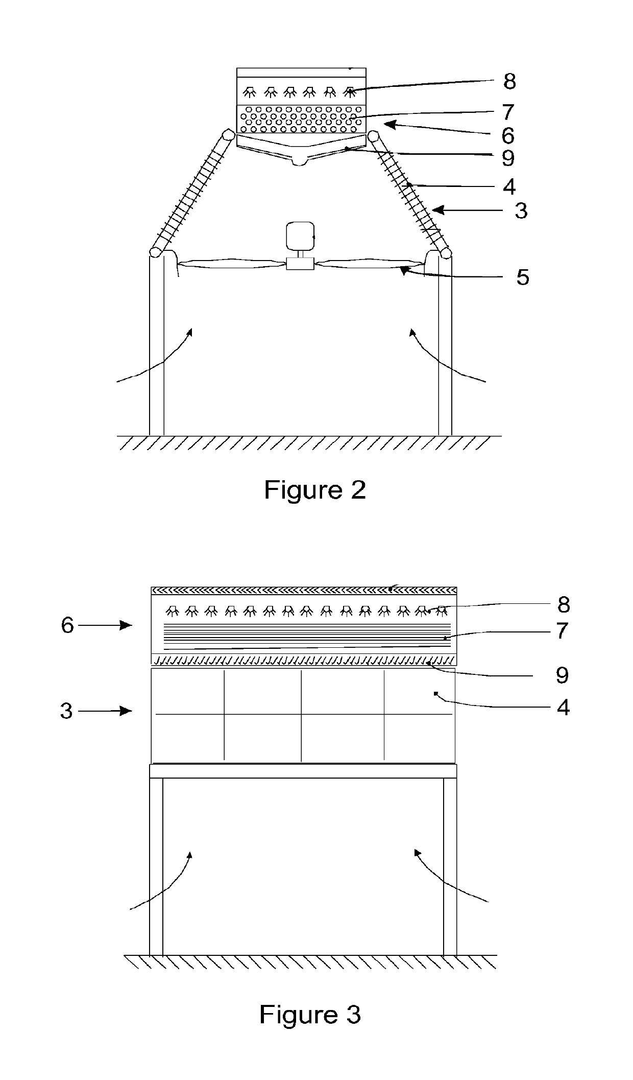
[0007]Further features of the invention provide for an arrangement of spray nozzles to be installed above the tube bundle whereby water can be sprayed onto the tube bundle in order to provide the evaporatively cooled mode; for drift eliminators to be positioned above the arrangement of spray nozzles to inhibit loss of water in the form of airborne droplets; and for one or more collection troughs to be provided beneath the tube bundle for collecting run-off water and enabling recycling of excess deluge water.
[0015]The system of the invention has the potential of enhanced thermal performance during periods of high ambient temperatures, while having a lower overall water consumption rate than that of adiabatic pre-cooling of inlet air using a water spray to provide similar performance enhancement.

Problems solved by technology

Due to the decreasing availability and rising cost of cooling water, dry-cooling towers or air-cooled steam condensers are increasingly being used to dissipate heat into the environment in power plants that incorporate steam turbines.
Unfortunately, at higher ambient temperatures, the effectiveness of such cooling systems decreases and this results in a corresponding reduction in turbine efficiency.
Any such reduction in turbine output during hot periods may result in a significant loss in income, especially in areas where the demand and value of electrical energy during these periods is high.
Not only that, but the capacity of the cooling system may need to be increased in order to cater for higher ambient temperatures thereby representing an increased capital cost and accompanying increased electricity production costs.
However, the improvement achieved in this instance does not appear to be commensurate with the cost involved.
However, for the nozzles tested only between 60% and 70% of the spray water is evaporated and even the introduction of a drift eliminator cannot ensure that the finned surfaces of the heat exchange tubes remain dry.
The unevaporated water droplets that accumulate on the structure can lead to corrosion of the structure surfaces as well as undesirable rainback that may cause surface and ground water contamination.
Due to practical and cost considerations spray cooling of inlet air does not appear likely to find application in large air-cooled condensers.

Method used


Image

  • Dephlegmator
  • Dephlegmator
  • Dephlegmator

Examples


Embodiment Construction

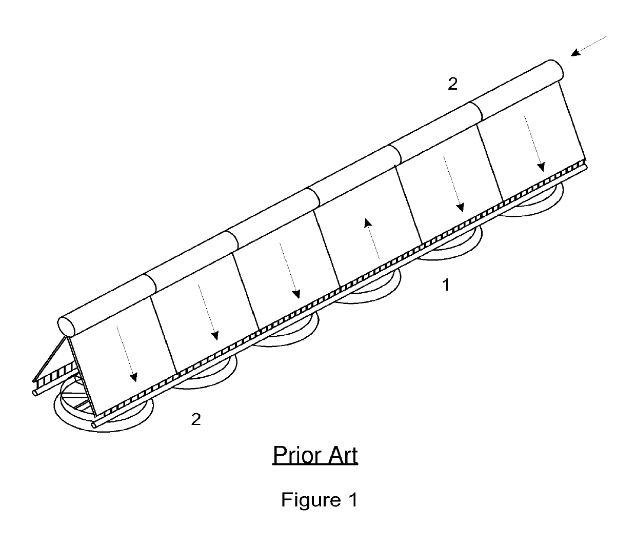
[0027]In the embodiment of the invention illustrated in FIGS. 1 to 5 of the drawings, a dephlegmator (1) according to the invention is incorporated into an existing A-frame type of air-cooled (dry) condenser installation comprising multiple primary condensers (2) in what is generally a usual arrangement.

[0028]The dephlegmator itself forms a terminal unit in the flow path of the spent steam emerging from a steam turbine operated electrical energy generating facility and, as more clearly illustrated in FIGS. 2 and 3, conforms to the present invention.

[0029]The dephlegmator thus comprises two stages connected in series wherein a first stage (3) is of generally conventional air-cooled reflux condenser construction consisting of multiple inclined finned tubes (4) that are similar to those used in a dry A-frame configuration although, if specially made for the purpose, they may be somewhat shorter. One or more fans (5) located in the region of the lower ends of the inclined finned tubes m...


PUM

PropertyMeasurementUnit
lengthaaaaaaaaaa
lengthaaaaaaaaaa
temperatureaaaaaaaaaa

Abstract

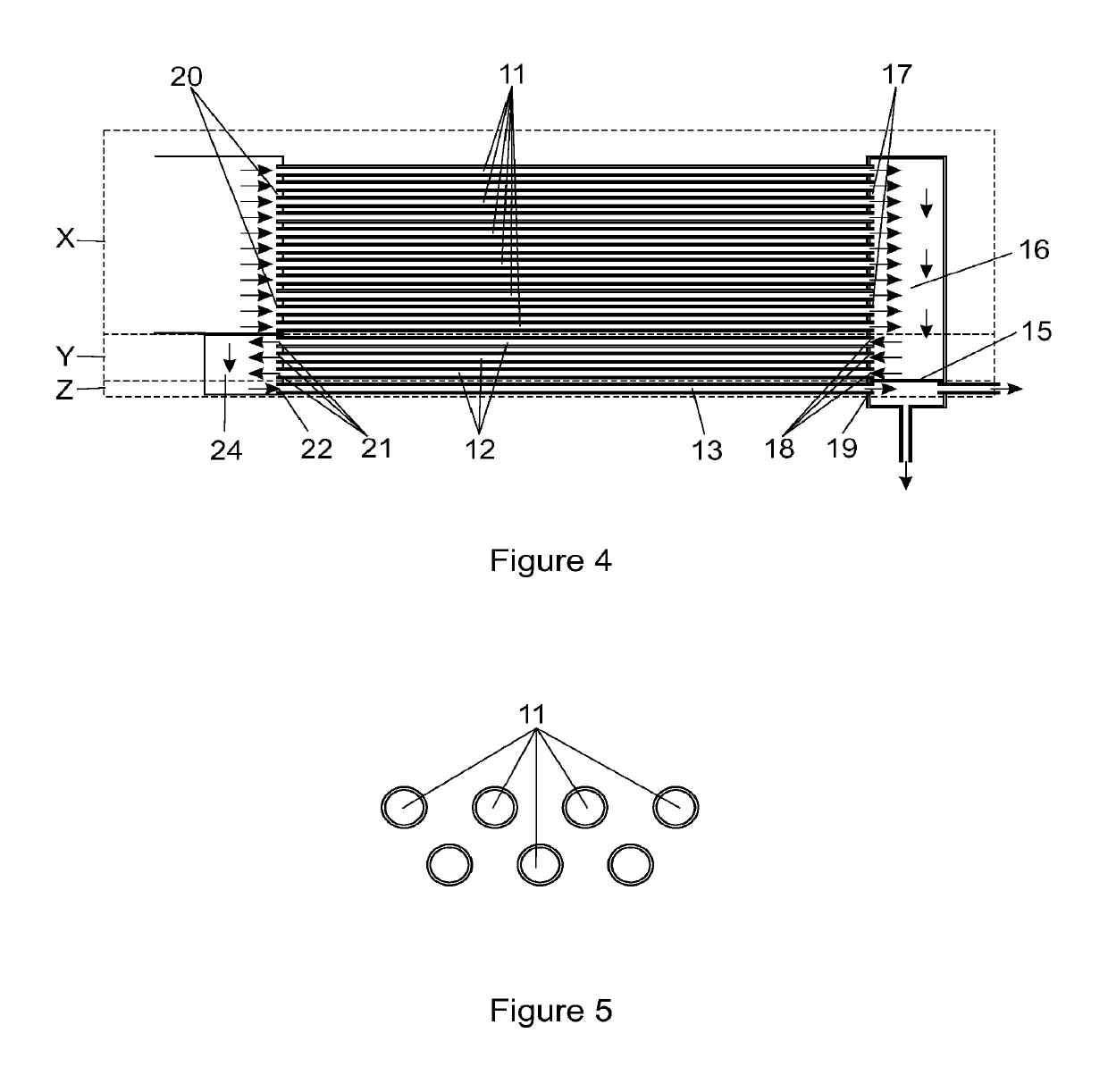
A dephlegmator is provided comprising two stages connected in series wherein a first stage includes an air-cooled reflux condenser and a second stage includes a generally horizontal tube bundle of smooth or finned tubes that can be operated selectively in either an air-cooled (dry) mode under selected ambient conditions or in a wet evaporatively cooled mode under other selected ambient conditions including that of elevated ambient temperature. Spray nozzles may be installed above the tube bundle whereby water can be sprayed onto the tube bundle. One or more collection troughs are preferably provided beneath the tube bundle for collecting run-off water and enabling recycling of excess deluge water. Preferably, the tube bundle comprises at least two, and preferably three groups of tubes communicating with each other wherein the second group of tubes has appreciably fewer tubes in it than the first group of tubes and any third group of tubes has appreciably fewer tubes in it than the second group of tubes.

Description

FIELD OF THE INVENTION[0001]This invention relates to a dephlegmator of the type employed in steam condensation installations in order to separate non-condensable gases from condensable gases. Such a dephlegmator assumes the form of a secondary reflux condenser that serves to remove non-condensable gases from what is generally steam in one form or another. A dephlegmator of this type is typically used in a steam condensation installation downstream of steam turbines used in electricity generating power plants and downstream of primary condensers.BACKGROUND TO THE INVENTION[0002]Due to the decreasing availability and rising cost of cooling water, dry-cooling towers or air-cooled steam condensers are increasingly being used to dissipate heat into the environment in power plants that incorporate steam turbines. Unfortunately, at higher ambient temperatures, the effectiveness of such cooling systems decreases and this results in a corresponding reduction in turbine efficiency. Any such ...

Claims


Application Information

Patent Timeline
Patent Type & Authority Patents(United States)
IPC IPC(8): B01D5/00F28B1/02F28B1/06F28B9/00F28D1/053
CPCB01D5/0009F28B1/06F28D1/05325F28B9/00F28F2210/10F28B1/02
Inventor REUTER, HANNO CARL RUDOLFKROGER, DETLEV G.
Owner STELLENBOSCH UNIVERSITY
Learn More