Printing device

a printing device and printing technology, applied in the direction of friction gearings, gearings, tension measurement, etc., can solve the problems of low drying efficiency, damage or loss of output, and the printing speed of the print output may not follow the print output speed, so as to reduce the work load of the operator and increase productivity. , the effect of reducing printing tim

Active Publication Date: 2019-06-11
KOSTECH INC
View PDF18 Cites 0 Cited by
  • Summary
  • Abstract
  • Description
  • Claims
  • Application Information

AI Technical Summary

Benefits of technology

[0027]According to an exemplary embodiment in the present disclosure, a printing device may be configured to include a moving device, allowing a winding unit to reciprocate between an outlet space of a printing unit and an inlet space thereof, and thus, in a work process in which a front end of a material is wound on the winding unit to be fixed thereto at the beginning of printing, moving the front end of the material from the outlet space of a printing unit to an inlet space thereof may be automatically carried out by the winding unit reciprocated by the moving device. Therefore, a workload of an operator may be reduced and a printing time may be also reduced, thereby ultimately increasing productivity and also preventing damage to a material and safety accidents.

Problems solved by technology

However, as compared to print output speed, which is faster than before, a drying speed of print output may not follow print output speed.
Therefore, in the case that dyeing, contamination, and the like, occurs, the output may be damaged or lost.
To improve this, various types of dryers have been developed, but drying speeds may be slow, so that drying efficiency may also be low.
Moreover, as a dryer takes up a lot of installation space, space utilization may be poor.
As described above, many complex problems remain.
However, since a printing speed is significantly reduced, there may be a problem of inefficiency in terms of production.
However, due to the direction changing roller R, a printed side 1a (an upper surface in the drawings) of the material 1 may come into contact with the direction changing roller R, whereby a problem in which the printed side 1a is contaminated may occur.
However, since such a large dryer D may takes up a considerable amount of installation space, only a relatively small number of printing devices may be located in a predetermined space.
Therefore, it may be inefficient in terms of productivity, and a problem in which it may not be able to be installed in a small installation space at all may further occur.

Method used


Image

  • Printing device
  • Printing device
  • Printing device

Examples


Embodiment Construction

[0033]In adding the reference numerals to the components of each drawing, although the same components are illustrated in different drawings, it is noted that they should have as many of the same numerals as possible. Further, in describing the present disclosure, when it is determined that the gist of the present disclosure may be rendered unclear due to a specific description of the related known configuration or function, a detailed description thereof will be omitted.

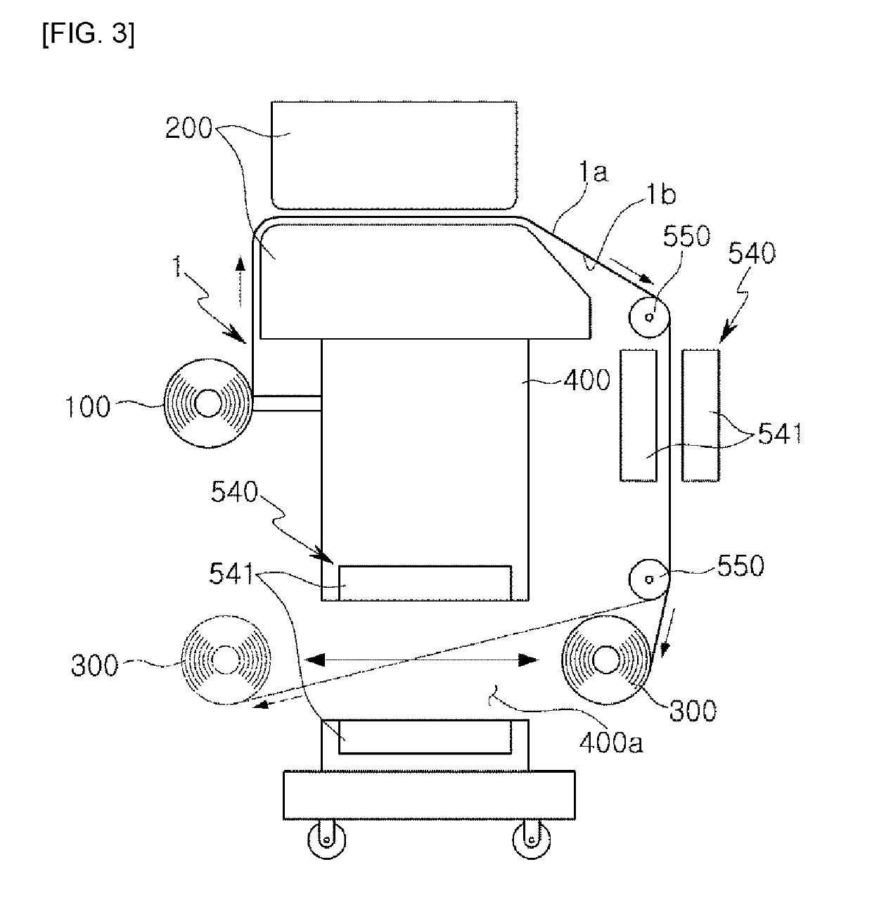
[0034]FIG. 3 is a schematic view of a printing device according to an exemplary embodiment in the present disclosure, and FIGS. 4 and 5 are views of a moving device according to various exemplary embodiments in the printing device of FIG. 3.

[0035]In addition, FIG. 6 is a view of a drying device according to a different exemplary embodiment in the printing device of FIG. 3.

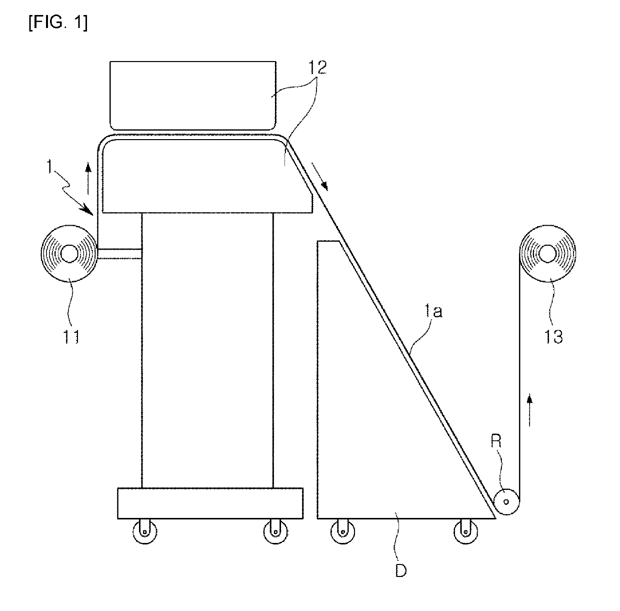
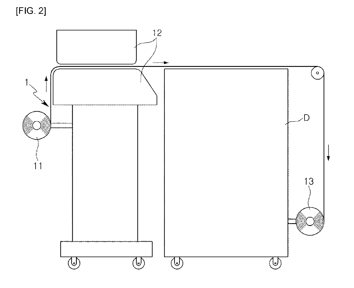
[0036]Referring to the drawings, a printing device may include a main body for printing on a material 1 and winding the material, and a moving dev...


PUM

PropertyMeasurementUnit
self weightaaaaaaaaaa
elastic forceaaaaaaaaaa
tensionaaaaaaaaaa

Abstract

A printing device includes a main body including a printing unit for printing on a material, and a winding unit for winding a printed material; and a moving device provided in the main body and configured to allow the winding unit to reciprocate between an outlet space of the printing unit and an inlet space thereof.

Description

TECHNICAL FIELD[0001]The present disclosure relates to a printing device, and particularly, to a printing device for printing text or an image on a material.BACKGROUND ART[0002]In the printing market, conventional hand work has rapidly changed to digital printing techniques, and print output speed has rapidly increasing due to improvements in the manufacturing technology of printing devices.[0003]However, as compared to print output speed, which is faster than before, a drying speed of print output may not follow print output speed. Therefore, in the case that dyeing, contamination, and the like, occurs, the output may be damaged or lost.[0004]To improve this, various types of dryers have been developed, but drying speeds may be slow, so that drying efficiency may also be low. Moreover, as a dryer takes up a lot of installation space, space utilization may be poor. As described above, many complex problems remain.[0005]In detail, in a printing device according to the related art, as...

Claims


Application Information

Patent Timeline
Patent Type & Authority Patents(United States)
IPC IPC(8): B41J15/16B41J15/04B41J11/00G01L5/04F16H19/04F16H7/02F16H1/16B41J3/407
CPCG01L5/04B41J15/16B41J3/4078F16H19/04B41J15/042F16H1/16F16H7/02B41J11/002B41J15/00B41J15/04B41J15/046B41J11/0021B41J11/00216B41J11/0022
Inventor MIN, KYUNG-WON
Owner KOSTECH INC
Why Eureka
Try Eureka