
Transmission structure of boxing machine

A transmission structure and cartoning machine technology, applied in packaging machines, packaging automatic control, packaging, etc., can solve the problems of low transmission efficiency, complex structure of the whole machine, high energy consumption, etc., to achieve improved transmission efficiency, superior transmission performance, transmission high efficiency effect

Pending Publication Date: 2020-12-18
义乌市科宏包装机械设备有限公司
View PDF0 Cites 0 Cited by
  • Summary
  • Abstract
  • Description
  • Claims
  • Application Information

AI Technical Summary

Problems solved by technology

[0002] The cartoning machine in the prior art is composed of multiple mechanisms. In addition to the main motor, each mechanism is driven by other motors, and some actions are also driven by cylinders, which leads to the inability of the transmission of each mechanism to be integrated. The synchronization is poor, and the transmission Low efficiency and high energy consumption make the structure of the whole machine complex and occupy a large space; and once the phenomenon of material shortage, package shortage, package collision, and jamming occurs, the parts that have this phenomenon will stop, but because each mechanism uses different power drive, causing other mechanisms to still be running and unable to stop synchronously, resulting in damage to materials and machines, resulting in unnecessary losses; cartoning machines in the prior art generally fold and paste cartons before loading items , because the paper box has just been pasted, the carton is not yet dry, and it is easy to be damaged in the follow-up action. At the same time, because the carton has been pasted, the items are blocked when the box is packed, the speed is slow, the efficiency is low, and it is easy to damage

Method used


Image

  • Transmission structure of boxing machine
  • Transmission structure of boxing machine
  • Transmission structure of boxing machine

Examples


Embodiment Construction

[0025] The following will clearly and completely describe the technical solutions in the embodiments of the present invention with reference to the accompanying drawings in the embodiments of the present invention. Obviously, the described embodiments are only some, not all, embodiments of the present invention. Based on the embodiments of the present invention, all other embodiments obtained by persons of ordinary skill in the art without making creative efforts belong to the protection scope of the present invention.

[0026] In the description of the present invention, it should be noted that the terms "upper / lower end", "inner", "outer", "front end", "rear end", "both ends", "one end", "another end" etc. indicate The orientation or positional relationship is based on the orientation or positional relationship shown in the drawings, and is only for the convenience of describing the present invention and simplifying the description, rather than indicating or implying that the...


PUM


Abstract

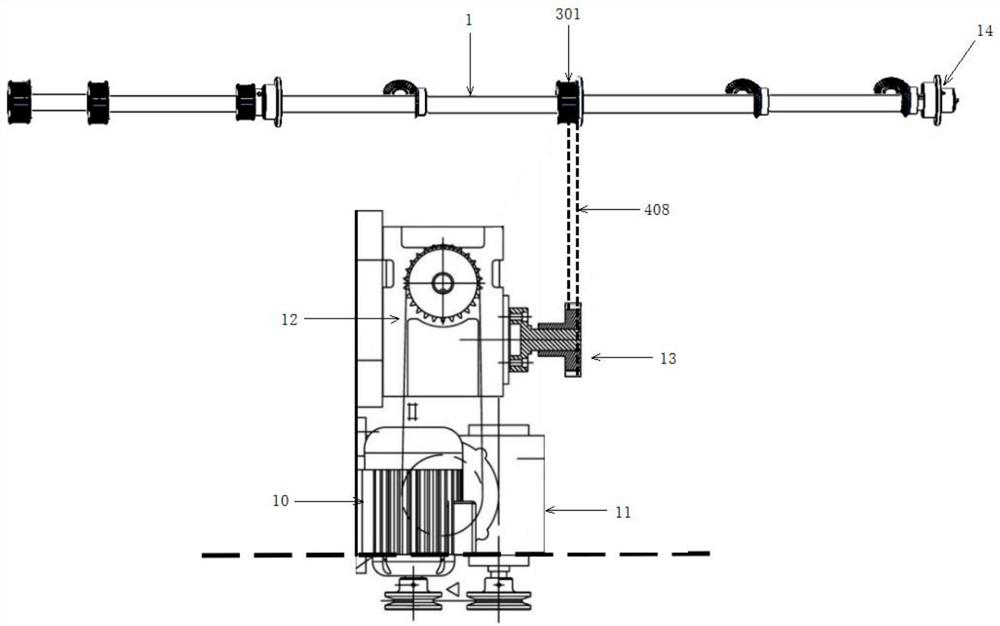
The invention discloses a transmission structure of a boxing machine. The transmission structure comprises a first transmission shaft and is characterized in that a first reversing bevel gear, a second reversing bevel gear, a first chain wheel, a third reversing bevel gear, a second chain wheel, a third chain wheel and a fourth chain wheel are arranged on the first transmission shaft at intervals.The first transmission shaft is arranged, and the first transmission shaft sequentially connects a boxing conveying mechanism, an inner bag feeding mechanism, a plane paper box discharging mechanism,a bag and box pushing mechanism, a box folding mechanism, a box pasting mechanism and a box discharging pushing mechanism into a whole through the multiple chain wheels and chains with different diameters. Linkage of all the mechanisms is achieved through driving of one motor, the transmission performance is excellent, the transmission efficiency is high, synchronism is good, and energy consumption is lower. Full-automatic operation of inner bag feeding, paper box discharging, bag pushing and box entering, edge folding forming, glue coating and box pasting and orderly discharging is achievedthrough close cooperation of all the mechanisms, and the technological process of boxing, box folding and box pasting is achieved.

Description

technical field [0001] The invention relates to the field of packaging equipment, in particular to a transmission structure of a cartoning machine. Background technique [0002] The cartoning machine in the prior art is composed of multiple mechanisms. In addition to the main motor, each mechanism is driven by other motors, and some actions are also driven by cylinders, which leads to the inability of the transmission of each mechanism to be integrated. The synchronization is poor, and the transmission Low efficiency and high energy consumption make the structure of the whole machine complex and occupy a large space; and once the phenomenon of material shortage, package shortage, package collision, and jamming occurs, the parts that have this phenomenon will stop, but because each mechanism uses different power drive, causing other mechanisms to still be running and unable to stop synchronously, resulting in damage to materials and machines, resulting in unnecessary losses; ...

Claims


Application Information

Patent Timeline
Patent Type & Authority Applications(China)
IPC IPC(8): B65B65/02B65B43/20B65B43/24B65B43/52B65B35/20B65B35/24B65B51/02B65B57/04
CPCB65B65/02B65B43/205B65B43/24B65B43/52B65B35/20B65B35/24B65B51/02B65B57/04
Inventor 肖德光
Owner 义乌市科宏包装机械设备有限公司
Learn More