Linear light emitting diode luminaires

a light-emitting diode and luminaire technology, applied in the direction of elongated light sources, semiconductor devices of light sources, lighting and heating apparatus, etc., can solve the problems of own design challenges, difficult to efficiently direct all of the emitted light to the intended usable area of lighting applications, and less desirable sources of fluorescent lamps for energy-efficient lighting applications. , to achieve the effect of low cost/economical, low cost and easy manufacturing

Active Publication Date: 2019-06-11
ABL IP HLDG
View PDF14 Cites 6 Cited by
  • Summary
  • Abstract
  • Description
  • Claims
  • Application Information

AI Technical Summary

Benefits of technology

[0003]It would be desirable to have a minimally complex, low cost / economical means of providing for the distribution of point source light, for example an array of LEDs, from a luminaire intended for a general lighting application, wherein the physical structures and components of the luminaire are relatively easy to manufacture with low-cost materials and are relatively easily to assemble to create a relatively low cost, energy efficient and aesthetically pleasing functional luminaire.

Problems solved by technology

Fluorescent lamps have become a less desirable source for energy efficient lighting applications since they emit light in 360 degrees.
This makes it hard to efficiently direct all of the emitted light to the intended usable area of the lighting application.
However, while LEDs are more energy efficient, they present their own design challenges for lighting applications.
In addition, since LEDs are point sources requiring dispersion in lighting applications, dispersed LED light will travel across a wide range of angles that will either be: (1) absorbed within the luminaire and create efficiency loss; (2) redirected out of the luminaire but beyond the intended usable area; (3) redirected out of the luminaire but unevenly distributed in the intended usable area, or (4) redirected out of the luminaire and evenly distributed across the intended usable area.
Therefore, there are difficult design challenges to properly dispersing light from a row of LEDs into a useful and efficient light distribution.
LED luminaire designs that fail to achieve even dispersion and distribution across the intended usable area, and fail to account for the wide range of angles for emitted light, will yield poor performance, including unacceptable glare and poor aesthetics in those lighting applications.

Method used


Image

  • Linear light emitting diode luminaires
  • Linear light emitting diode luminaires
  • Linear light emitting diode luminaires

Examples


Embodiment Construction

[0021]We have now devised simple and relatively inexpensive luminaire designs that redistribute the light from a row of LEDs into a continuous bar of light of relatively uniform luminance and then disperses that light in a desirable distribution with a high energy efficiency.

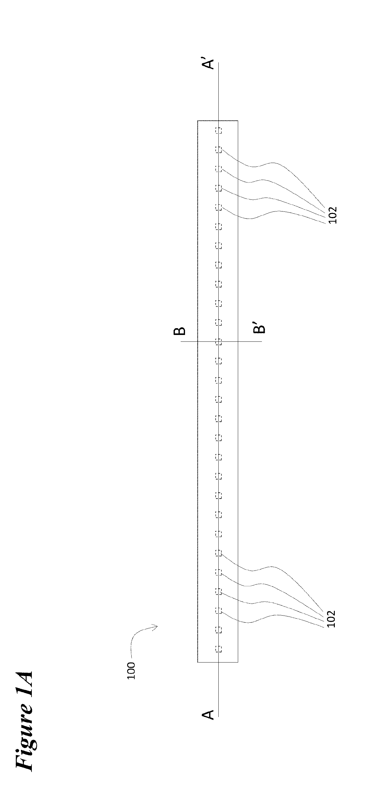
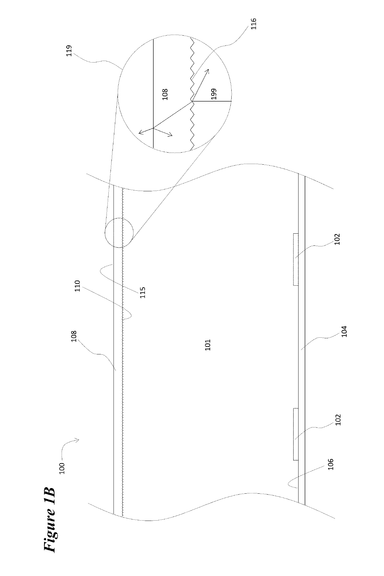
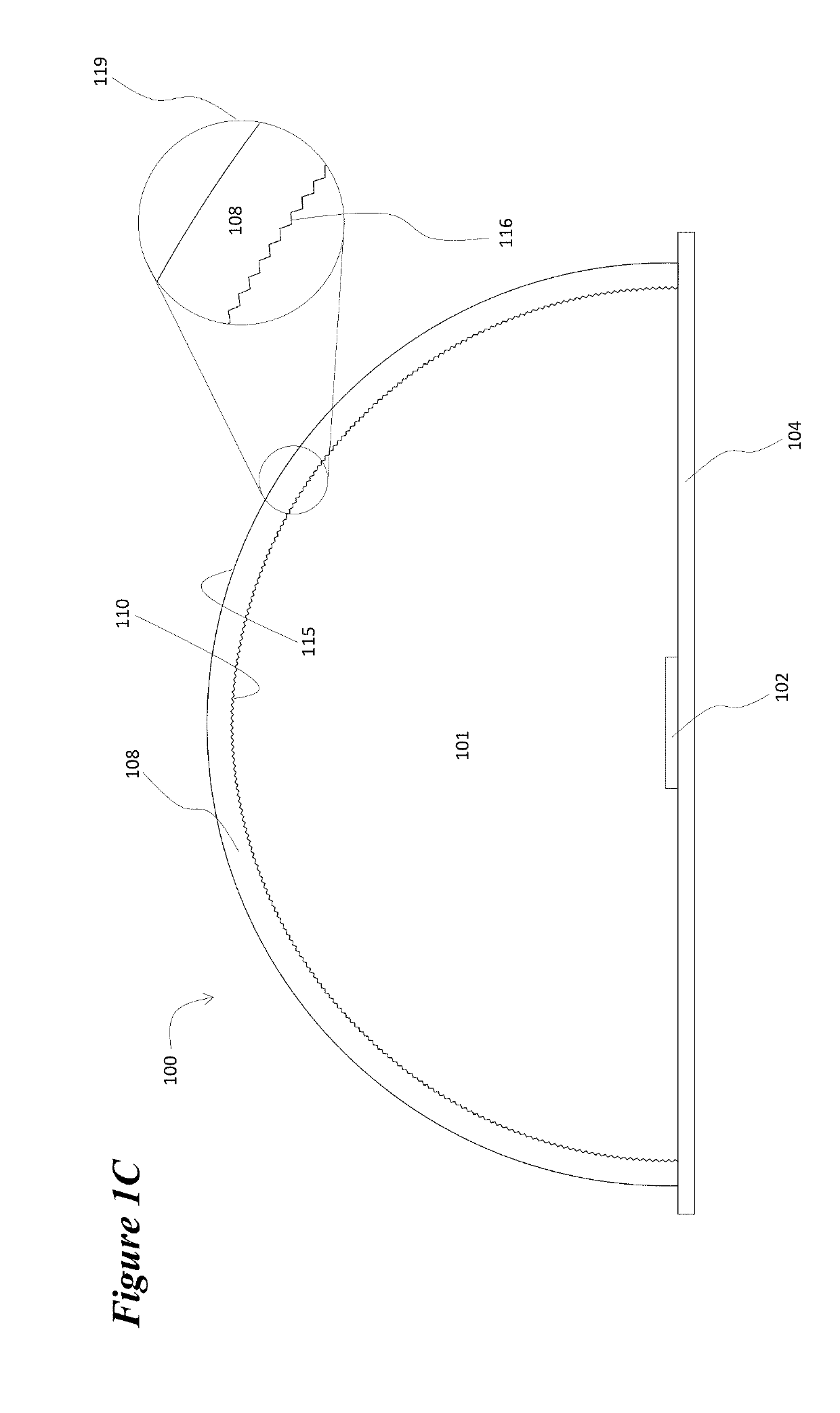
[0022]The device 100 depicted in FIGS. 1A, 1B, and 1C illustrates the general nature of the invention, but also illustrates an issue with regard to its implementation. FIG. 1A depicts the luminaire in a plan view with the location of the row of LEDs 102 interior to the luminaire illustrated. FIG. 1B depicts a cross-sectional view of a segment of the luminaire along axis A-A′ that is shown in FIG. 1A. LEDs 102 are mounted or attached to substrate 104. This substrate may be a printed circuit board, a flexible plastic tape, or the case that encloses the luminaire. In any case the substrate provides the electrical interconnections that connect the LEDs to drive electronics (not shown). Surface 106 of substrate 104 m...


PUM


Abstract

A minimally complex, low cost / economical luminaire that distributes point source light for general lighting applications, the luminaire having a substrate with a linear array of discrete light sources positioned to emit light into an air-filled cavity and a light redirecting assembly on the other side the air-filled cavity, the assembly comprising a clear, light transmissive rigid cover and a clear, light transmissive semi-rigid flexible film positioned between the cover and the substrate, wherein the film is non-adhesively secured within the luminaire and flexed to generally conform to the shape of the cover and wherein the surface of the film facing into the air-filled cavity comprises an array of optical relief structures extending into the air-filled cavity.

Description

BACKGROUND[0001]Light emitting diodes (LEDs) are an energy efficient, highly reliable technology that is finding considerable utility in replacing fluorescent lamps in many lighting applications. Fluorescent lamps have become a less desirable source for energy efficient lighting applications since they emit light in 360 degrees. This makes it hard to efficiently direct all of the emitted light to the intended usable area of the lighting application. However, while LEDs are more energy efficient, they present their own design challenges for lighting applications. Specifically, LEDs are point sources as opposed to continuous / extended sources of light. This concentration of point source light needs to be evenly dispersed and distributed across the intended usable area for the lighting application. In addition, since LEDs are point sources requiring dispersion in lighting applications, dispersed LED light will travel across a wide range of angles that will either be: (1) absorbed within...

Claims


Application Information

Patent Timeline
Patent Type & Authority Patents(United States)
IPC IPC(8): F21V7/00F21V3/00F21S4/20F21V17/16F21Y103/10F21Y115/10
CPCF21S4/20F21V3/00F21V17/164F21Y2115/10F21Y2103/10
Inventor MAGNO, JOHN N.TEATHER, ERIC W.
Owner ABL IP HLDG
Why Eureka
Try Eureka