
Energy cable having a crosslinked electrically insulating layer, and method for extracting crosslinking by-products therefrom

a technology of crosslinking and electrical insulation, which is applied in the direction of insulated conductors, power cables, cables, etc., can solve the problems of increasing to a large extent the time and production costs of dc energy cables, voids, and electrical discharges, so as to reduce temperature and/or duration, increase productivity, and reduce manufacturing costs

Active Publication Date: 2019-06-18
PRYSMIAN SPA
View PDF43 Cites 3 Cited by
  • Summary
  • Abstract
  • Description
  • Claims
  • Application Information

AI Technical Summary

Benefits of technology

[0010]The Applicant has faced the problem of eliminating the high temperature, long lasting degassing process of the energy cable cores having a crosslinked insulating layer, or at least to reduce temperature and / or duration of the same, so as to increase productivity and reduce manufacturing costs. The above goal should be achieved without increasing the complexity of the cable production and, of course, without any detrimental effects on cable performance even after many years from installation.
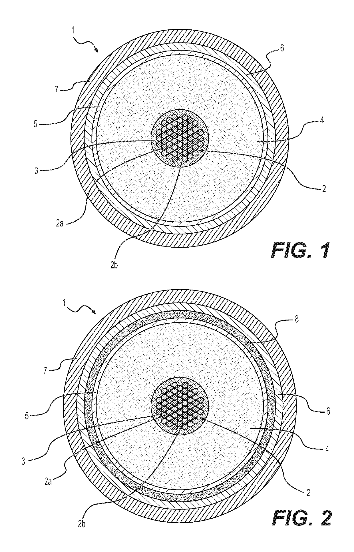
[0011]The above problem and others that will appear more clearly from the following description can be solved by providing the cable core with zeolite particles placed in the vicinity of the crosslinked insulating layer, more specifically in the cable core, for instance within the cable conductor and / or on the outer semiconducting layer. The zeolite particles are able to extract and absorb, very efficiently and irreversibly, the by-products deriving from the cross-linking reaction, so as to avoid space charge accumulation in the insulating material during cable lifespan.
[0018]In particular, the zeolite particles substantially irreversibly absorb some of the crosslinking by-products during the heating step. During the heating step, a fraction of crosslinking by-products which is gaseous at ambient temperature, such as methane, or which has a low boiling point, is eliminated by causing it to diffuse out of the cable core. Preferably, the heating step is carried out at a temperature of from 70° C. to 80° C., for a time from 7 to 15 days. The presence of zeolite particles in the vicinity of the crosslinked electrically insulating layer avoids to extend the degassing procedure for a longer time (usually from 15 to 30 days), for removing high-boiling by-products, such as cumyl alcohol and acetophenone.
[0031]According to a fourth embodiment, the zeolite particles are placed both within voids among the filaments of the electric conductor, and into or in contact with a semiconducting layer, preferably the outer semiconducting layer. In that way, the effect of the zeolite particles is exerted on both sides of the electrically insulating layer, and therefore the extraction and absorption of the crosslinking by-products is more efficient.
[0036]According to the above preferred embodiments, it is apparent that the zeolite particles can be placed in the vicinity of the crosslinked electrically insulating layer by means of cable elements that are already usual components of energy cables, such as hygroscopic yarns or tapes or buffering filling materials, thus avoiding supplementing the cable with an additional component which would not be necessary for a conventional cable. This remarkably reduces cable manufacturing costs and time. The above advantage does not exclude the possibility of providing the energy cable with zeolite particles by means of one or more additional components purposively placed into the cable to obtain extraction and absorption of the crosslinking by-products.
[0044]As regards the amount of zeolite particles to be placed in the vicinity of the crosslinked electrically insulating layer, it can vary within a wide range and mainly depends on the type of zeolite, the amount of by-products to be eliminated, the thickness of the insulating layer, the degassing temperature, and the final target by-products content. According to preliminary evaluations, assuming a final target of 0.32 wt % of cumyl alcohol content, the zeolite particles are preferably present in an amount of from 70 g / m to 1000 g / m for a 25 mm insulating thickness and from 27 g / m to 450 g / m for a 15 mm insulating thickness, more preferably from 70 g / m to 210 g / m for a 25 mm insulating thickness and from 27 g / m to 80 g / m for a 15 mm insulating thickness, the units being expressed as amount of zeolite particles (in grams) versus the length of the cable (in meters). In view of the above ranges and indications, the skilled person is able determine a suitable amount of zeolite particles to be added to a given insulation layer without undue burden.

Problems solved by technology

In the presence of a continuous electrical field, such by-products, being entrapped within the crosslinked material, cause an accumulation of space charges which may cause electrical discharges and eventually insulation piercing, particularly in direct current (DC) energy cables.
This increases to a large extent the time and production costs of DC energy cables.
The moisture that is formed by the above degradation may cause appearance of voids and bow-tie trees with consequent degradation of the insulating material.

Method used


Image

  • Energy cable having a crosslinked electrically insulating layer, and method for extracting crosslinking by-products therefrom
  • Energy cable having a crosslinked electrically insulating layer, and method for extracting crosslinking by-products therefrom
  • Energy cable having a crosslinked electrically insulating layer, and method for extracting crosslinking by-products therefrom

Examples


examples 1-7

[0067]Some tests were carried out to evaluate the ability of different materials to absorb cumyl alcohol, one of the major by-products deriving from crosslinking reaction of polyethylene with cumyl peroxide. Each material in the form of fine particles was placed in an amount of about 0.6 g in little bags made from a non-woven polyester fabric, which are porous so as to allow free migration of cumyl alcohol molecules.

[0068]The little bags of the materials to be tested were placed in a cylinder made from aluminum, having a plurality of recesses to host the samples and a central circular cavity where a glass beaker containing cumyl alcohol was placed. In one of the recesses a fully degassed sample of crosslinked polyethylene (XLPE) was placed to measure the solubility of cumyl alcohol in that material as reference. The cylinder, containing the little bags of the materials to be tested, the sample of XLPE and the cumyl alcohol, was fastened with a closing plate provided with an O-ring t...

examples 8-11

[0073]In order to simulate the conditions in an energy cable, the absorption ability of zeolite CBV 600 was evaluated according to the following method.

[0074]The crosslinkable Borealis LE 4253, commonly used as insulating material for DC energy cables, was used to produce discs of freshly crosslinked polyethylene as disclosed above.

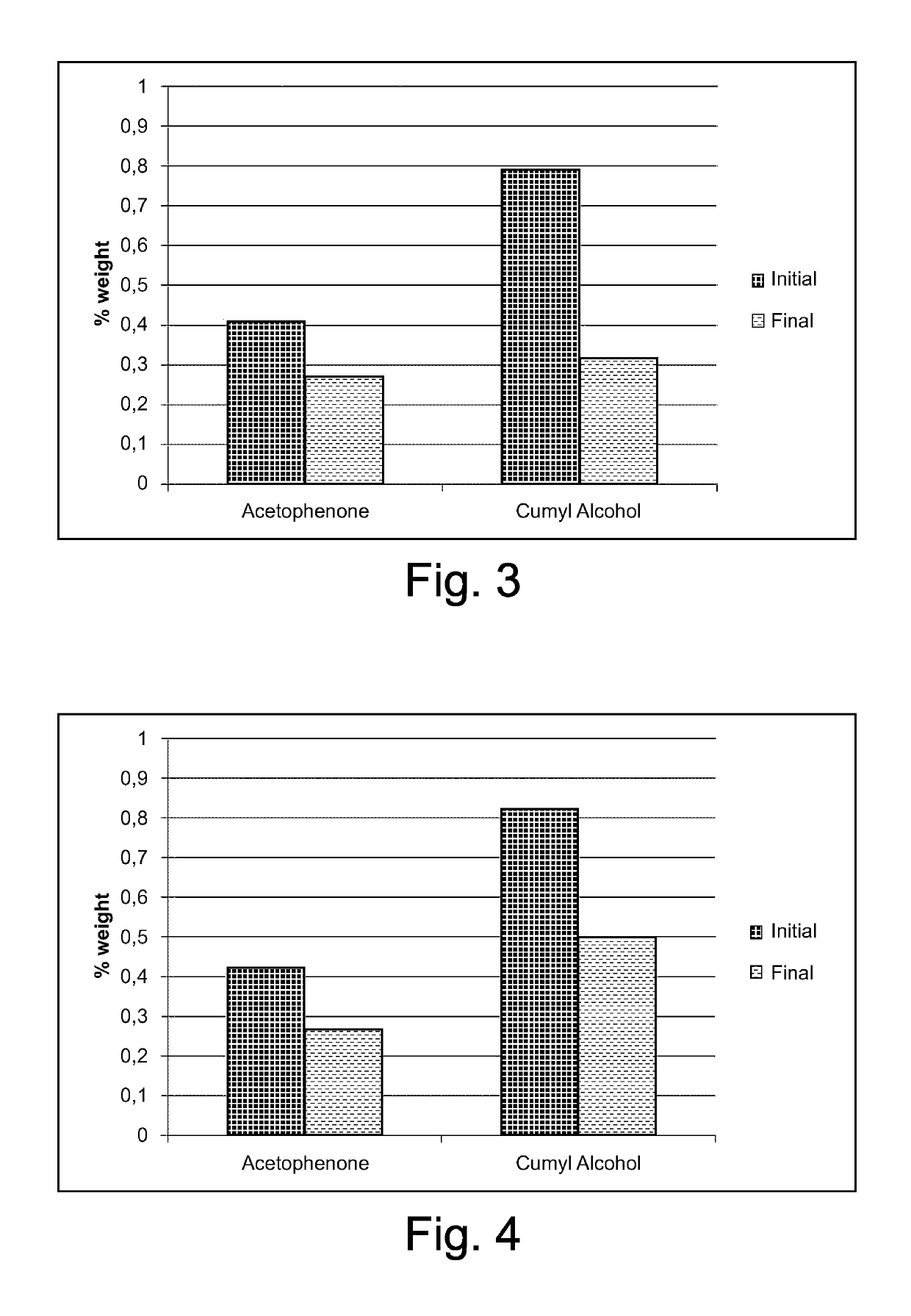
[0075]A disc of freshly crosslinked LE 4253 (diameter 140 mm, thickness 2.87 mm) was placed in a cylinder similar to that of Examples 1-7, but devoid of recesses and cavity to host samples and container, and three little bags as described in Examples 1-7 containing zeolite CBV 600 were placed on the disc (weight ratio zeolite / LE 4253=0.013). The testing device was closed airtight and maintained at the testing temperature (60° C. or 40° C.) for 16 days. In the diagrams of FIGS. 3-4, the amounts of acetophenone and cumyl alcohol in the LE 4253 disc as such (i.e. just after crosslinking) and after contact with the zeolite are reported. A remarkable reduction...

examples 12-13

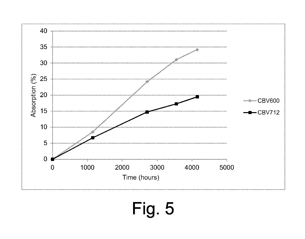
[0076]In order to evaluate the ability of the zeolite particles to absorb the crosslinking by-products even during storage at room temperature, a sample of zeolite CBV600 (Example 12) or of zeolite CBV712 (Example 13) was placed into a bag made from Polylam™, where also a small container containing cumyl alcohol was placed. The bag was hermetically closed. The amount of cumyl alcohol absorbed by the zeolite sample was measured over time by extracting the zeolite sample from the bag after a certain time. The results are reported in the diagram of FIG. 5, from which it appears that the zeolite continued to absorb cumyl alcohol even after more than 4000 hours of exposure at 23° C. From these data, we can derive that the zeolite particles placed in the vicinity of the insulating layer of an energy cable should be able to eliminate the crosslinking by-products not only during degassing heating but also during storage of the cable at ambient temperature.


PUM

PropertyMeasurementUnit
molar ratioaaaaaaaaaa
temperatureaaaaaaaaaa

Abstract

An energy cable includes, at least one cable core including an electric conductor, a crosslinked electrically insulating layer, and zeolite particles placed in the cable core. The zeolite particles are able to extract and absorb, very efficiently and irreversibly, the by-products deriving from the cross-linking reaction, so as to avoid space charge accumulation in the insulating material during cable lifespan. A method for extracting crosslinking by-products from a cross-linked electrically insulating layer of an energy cable core, which includes manufacturing the energy cable core containing zeolite particles, heating the energy cable core up to a temperature causing migration of the crosslinking by-products from the crosslinked electrically insulating layer; and then placing a metal screen around the energy cable core.

Description

CROSS REFERENCE TO RELATED APPLICATION[0001]This application is a national phase application based on PCT / IB2013 / 059562, filed Oct. 23, 2013, the content of which is incorporated herein by reference.BACKGROUND OF THE INVENTION[0002]The present invention relates to an energy cable having a crosslinked electrically insulating layer, and to a method for extracting crosslinking by-products therefrom.[0003]Cables for transporting electric energy generally include at least one cable core. The cable core is usually formed by at least one conductor sequentially covered by an inner polymeric layer having semiconducting properties, an intermediate polymeric layer having electrically insulating properties, an outer polymeric layer having semiconducting properties. Cables for transporting medium or high voltage electric energy generally include at least one cable core surrounded by at least one screen layer, typically made of metal or of metal and polymeric material. The screen layer can be mad...

Claims


Application Information

Patent Timeline
Patent Type & Authority Patents(United States)
IPC IPC(8): H01B9/00H01B7/00H01B3/00H01B13/22C01B39/46H01B13/00
CPCH01B7/0009C01B39/46H01B3/006H01B13/002H01B13/22
Inventor SICA, RODOLFOANELLI, PIETRO RICHARD
Owner PRYSMIAN SPA
Learn More