Piercing processing method and laser processing machine

a laser processing machine and processing method technology, applied in metal-working equipment, welding equipment, manufacturing tools, etc., can solve the problems of ineffective action of laser beam energy on workpieces, inability to shorten the piercing processing time,

Active Publication Date: 2019-06-25
AMADA HLDG CO LTD
View PDF20 Cites 0 Cited by
  • Summary
  • Abstract
  • Description
  • Claims
  • Application Information

AI Technical Summary

Benefits of technology

[0006]The present invention has discovered that, in a configuration in which a laser processing head is equipped with a condensing lens, at a time of carrying out a laser cutting processing on a thick plate, in order to carry out a piercing processing, the piercing processing on the thick plate can be carried out efficiently by setting a ratio Zr / d of a condensed beam diameter d and a Rayleigh length Zr of the laser beams due to the condensing lens to be in a prescribed range.
[0021]According to the present invention, as it is one that carries out a piercing processing by setting a ratio of a condensed beam diameter d and a Rayleigh length Zr of the laser beams to be in an appropriate range, it is one that can carry out a piercing processing on a thick plat efficiently.

Problems solved by technology

However, in the laser processing machine mounted with a fiber laser oscillator, even when the piercing processing method as described in said Patent Document 1 is practiced, it has not been possible to shorten the piercing processing time significantly.
As this axicon lens forms ring shaped beams from incident laser beams, there has been a possibility that the energy of the laser beams is not being able to act on the workpiece effectively at a time of the piercing processing on the workpiece.

Method used


Image

  • Piercing processing method and laser processing machine
  • Piercing processing method and laser processing machine
  • Piercing processing method and laser processing machine

Examples


Embodiment Construction

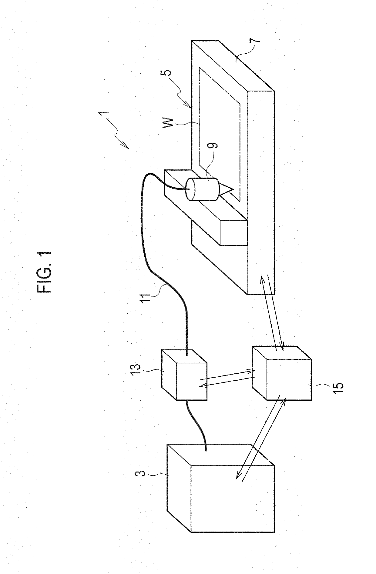
[0025]As shown in FIG. 1 conceptually and schematically, a laser processing machine (a laser processing system) 1 according to an embodiment of the present invention is equipped with a laser oscillator 3 and a processing machine body 5. The above noted laser oscillator 3 is a laser oscillator such as a fiber laser oscillator and the like that oscillates laser beams with wavelengths in 1 μm band. Note that it is also possible for said laser oscillator 3 to make semiconductor laser beams with a seed light in a wavelength of less than 1 μm, as a direct diode laser. Said processing machine body 5 is equipped with a laser processing head 9, which is freely positioning relative movements in X, Y and Z axes directions with respect to a workpiece W of a thick plate shape such as a mild steel plate and the like that is mounted on a workpiece table 7, for example. This laser processing head 9 is equipped with a condensing lens (omitted to be shown in figures). Note that said laser oscillator ...


PUM

PropertyMeasurementUnit
wavelengthsaaaaaaaaaa
thicknessaaaaaaaaaa
wavelengthaaaaaaaaaa

Abstract

A piercing processing method and a laser processing machine capable of carrying out a piercing processing on a thick plate in short time are provided. It is a processing method for carrying out a piercing processing on a metallic material by laser beams with wavelengths in 1 μm band, where the piercing processing is carried out by maintaining a range of 8≤Zr / d≤12 when a condensed beam diameter of the laser beams is set to be d and a Rayleigh length of the laser beams is set to be Zr. At that time, a focal position of the laser beams is set to be on a surface of a workpiece or an external of the workpiece. Then, a beam profile of the laser beams is such that the laser beams of a single mode are converted into a bowler hat shape by a beam quality tunable device.

Description

TECHNICAL FIELD[0001]The present invention relates to a piercing processing method and a laser processing machine for carrying out a piercing processing, at a time of carrying out a laser cutting processing on a sheet metallic material by laser beams with wavelengths in 1 μm band of a solid state laser or a fiber laser, for example, and in further detail, to a piercing processing method and a laser processing machine capable of carrying out a piercing processing on a thick plate of a mild steel plate in short time.BACKGROUND ART[0002]In the case of carrying out the laser cutting processing on a plate shaped workpiece such as a mild steel plate, the piercing processing is carried out on the above noted workpiece and the laser cutting processing on the workpiece is started from this piercing processed position. The above noted piercing processing is carried out almost instantaneously (several hundreds msec) in the case where the workpiece is a thin plate, so that there are not much of...

Claims


Application Information

Patent Timeline
Patent Type & Authority Patents(United States)
IPC IPC(8): B23K26/382B23K26/064B23K26/06
CPCB23K26/382B23K26/0665B23K26/064B23K26/0648
Inventor LI, RUOTAOISHIGURO, HIROAKI
Owner AMADA HLDG CO LTD
Why Eureka
Try Eureka