
Retainer and tapered roller bearing

a tapered roller bearing and tapered roller bearing technology, which is applied in the direction of rolling contact bearings, shafts and bearings, rotary bearings, etc., can solve the problems of reducing increasing difficult to effectively reduce the rotation torque of the bearing, so as to reduce the shear resistance of oil, reduce the contact length, and reduce the stirring resistance of oil

Active Publication Date: 2019-06-25
NTN CORP
View PDF30 Cites 2 Cited by
  • Summary
  • Abstract
  • Description
  • Claims
  • Application Information

AI Technical Summary

Benefits of technology

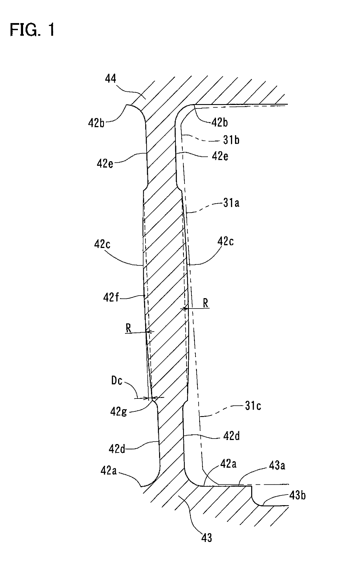
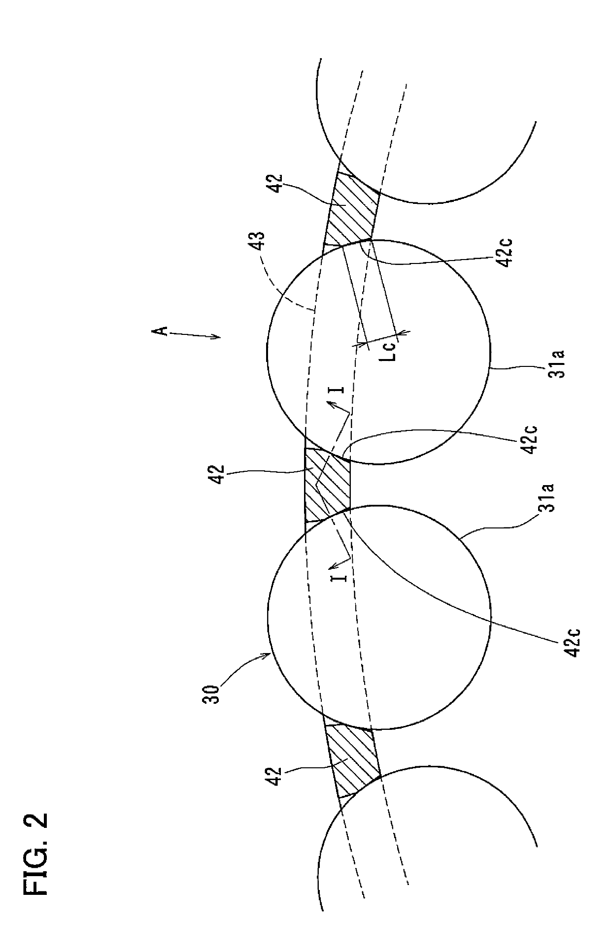
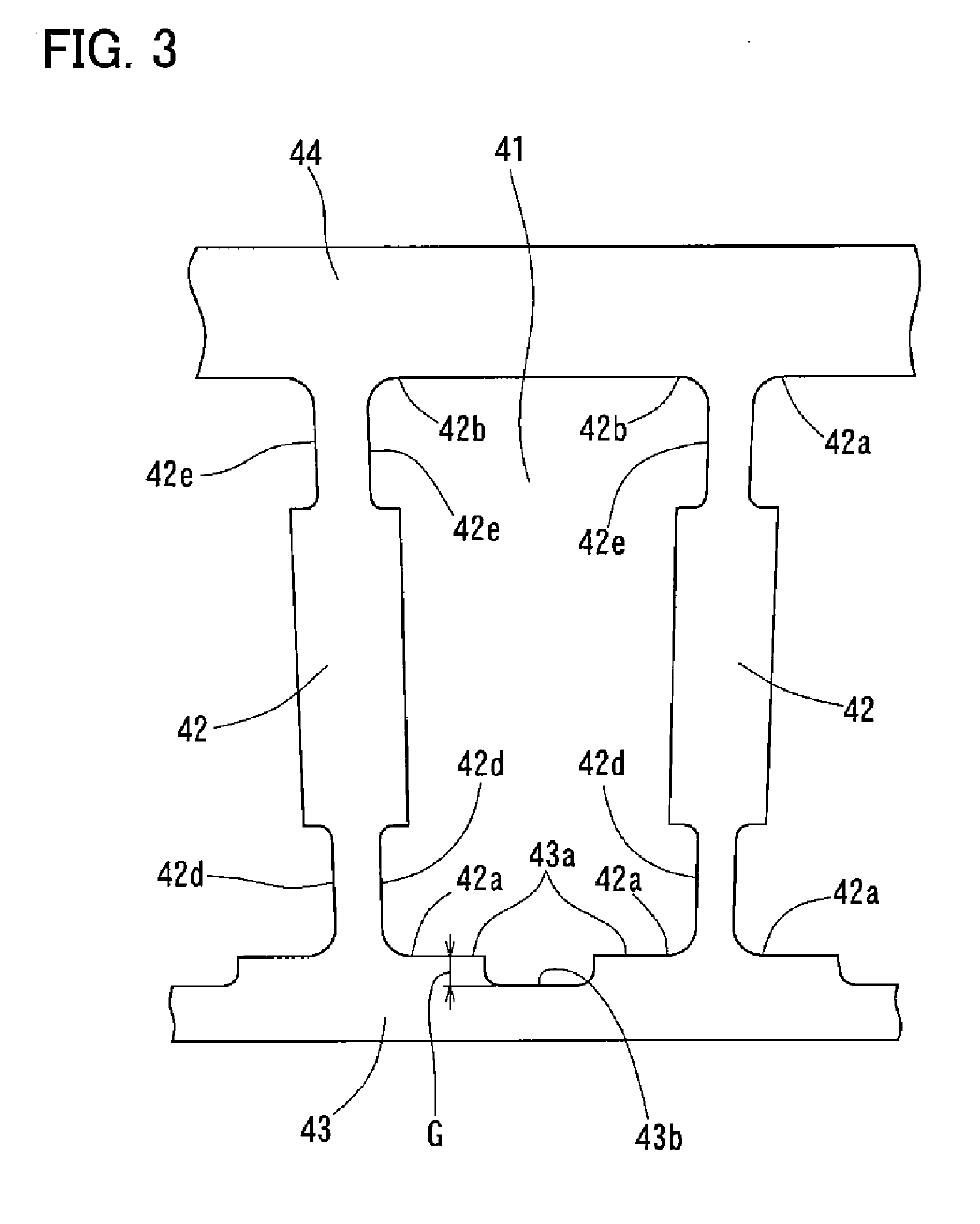
[0011]In the first aspect of the invention, the first recessed surfaces of the crossbars allow oil that has flowed through the gap between the retainer and the inner race into the space between the retainer and the inner race to quickly flow into the space between the retainer and the outer race, thereby reducing the stirring resistance of oil. The combination of the first recessed surfaces and the second recessed surfaces of the crossbars reduces shear resistance of oil between the tapered rollers and the guide surfaces. The use of the convex guide surfaces, in combination with tapered rollers each including a rolling surface central portion having a straight generating line and located at the central portion of the entire length of the tapered roller, reduces the contact lengths between the guide surfaces and the tapered rollers, thereby reducing the bearing rotation torque.
[0012]In the second aspect of the invention, the third recessed surfaces of the first annular portion allow oil that has flowed through the gap between the retainer and the inner race into the space between the retainer and the inner race to quickly flow into the space between the retainer and the outer race, thereby reducing the stirring resistance of oil. Further, the use of the convex guide surfaces, in combination with tapered rollers each including a rolling surface central portion having a straight generating line and located at the central portion of the entire length of the tapered roller, reduces the contact lengths between the guide surfaces and the tapered rollers, thereby reducing the bearing rotation torque.
[0013]In a third aspect of the invention, since each guide surface is tapered, and has a length of not less than 5% and not more than 20% of the average diameter of the corresponding tapered roller, in a plane perpendicular to the center axis of the tapered roller, the oil film forming area is small, so that the shear resistance of oil between the tapered rollers and the crossbars is also small. Further, the use of the convex guide surfaces, in combination with tapered rollers each including a rolling surface central portion having a straight generating line and located at the central portion of the entire length of the tapered roller, reduces the contact lengths between the guide surfaces and the tapered rollers, thereby reducing the bearing rotation torque.

Problems solved by technology

The increase in such shear resistance also tends to increase rotation torque of the bearing.
Some other conventional retainers have recesses in the shape of cutouts formed in the annular portion of the retainer on its small-diameter side to allow oil that has flowed through a gap between the retainer and the inner race into the space between the retainer and the inner race to quickly flow into the space between the retainer and the outer race, thereby reducing the stirring resistance of oil.
This makes it difficult to effectively reduce the bearing rotation torque.

Method used


Image

  • Retainer and tapered roller bearing
  • Retainer and tapered roller bearing
  • Retainer and tapered roller bearing

Examples


first embodiment

[0036]Now referring to FIGS. 1-5, a tapered roller bearing according to the present invention is described, which includes, as shown in FIG. 4, an inner race 10 having an outer periphery formed with a raceway surface 11, and including a small flange 12 and a large flange 13; an outer race 20 having an inner periphery formed with a raceway surface 21; and a retainer 40 formed with pockets 41 in which tapered rollers 30 are received. As used herein, the words “circumferential direction”, “circumferential” and circumferentially” refer to the circumferential direction around the center axis of the bearing; the words “axial direction”, “axial” and “axially” refer to the direction of the center axis of the bearing; and the words “radial direction”, “radial” and “radially” refer to a direction perpendicular to the center axis of the bearing. The center axes of the inner race 10, the outer race 20, and the retainer 40 coincide with the center axis of the bearing.

[0037]As shown in FIG. 5, ea...

fifth embodiment

[0069]In an arrangement in which the crossbars are free of the first and second recessed surfaces, each convex guide surfaces may have a composite shape consisting of a plurality of curves having different radii of curvature, and or a straight line or lines smoothly connected together. The fifth embodiment, shown in FIG. 10, is such an example.

[0070]In the fifth embodiment of FIG. 10, the crossbars 70 are free of the first and second recessed surfaces so that each convex guide surface 71 extends the entire length of the crossbar 70 between the corresponding two rounded corners, with each guide surface 71 having a composite shape consisting of curves having different radii of curvature. In particular, as with the second embodiment, each guide surface 71 includes a central portion 71a having a first radius of curvature R1, the remaining portions 71b having a second radius of curvature R2.

[0071]In an arrangement in which the convex guide surfaces are provided, any or all of the first t...


PUM


Abstract

A retainer of a tapered roller bearing includes crossbars having guide surfaces which circumferentially contact the tapered rollers. The crossbars are also formed with first recessed surfaces and second recessed surfaces which are both in the form of cutouts circumferentially recessed from the respective guide surfaces to reduce stirring resistance and shear resistance of oil. To reduce the contact lengths between the rolling surface central portions of the tapered rollers and the guide surfaces, the guide surfaces are smoothly convex in the longitudinal direction of the tapered rollers.

Description

TECHNICAL FIELD[0001]This invention relates to a retainer formed with pockets for receiving tapered rollers, and a tapered roller bearing including such a retainer.BACKGROUND ART[0002]During operation of a tapered roller bearing, oil passing through the bearing is stirred by e.g., the rolling tapered rollers, and the stirring resistance of oil tends to increase rotation torque of the bearing. The crossbars of the retainer have guide surfaces that are circumferentially brought into contact with the tapered rollers in the pockets. This increases the shear torque (or shear resistance) of oil between the tapered rollers and the guide surfaces. The increase in such shear resistance also tends to increase rotation torque of the bearing. Trials have heretofore been made to reduce rotation torque of the bearing by modifying the shape of the retainer.[0003]For example, in order to reduce the shear resistance of oil by reducing the amount of oil flowing into the bearing, one conventional reta...

Claims


Application Information

Patent Timeline
Patent Type & Authority Patents(United States)
IPC IPC(8): F16C19/36F16C33/54F16C33/36F16C33/46
CPCF16C19/364F16C33/36F16C33/366F16C33/54F16C33/4676F16C2240/50F16C2240/30F16C2240/40
Inventor KAWAI, TAKASHI
Owner NTN CORP
Learn More