Stereo camera for vehicles

a stereo camera and vehicle technology, applied in the field of stereo camera for vehicles, can solve the problems of inconvenient use of image sensors for automobile use, inability to efficiently process the large number of pixels for elaborate image processing algorithms, and the use of such a high-resolution color image sensor is contrary to the inexpensive realization of driver assistance functions. , to achieve the effect of increasing resolution

Active Publication Date: 2019-06-25
CONTI TEMIC MICROELECTRONIC GMBH
View PDF18 Cites 1 Cited by
  • Summary
  • Abstract
  • Description
  • Claims
  • Application Information

AI Technical Summary

Benefits of technology

[0011]Starting from the above prior art, it is an object of at least one embodiment of the invention to create a stereo camera of the type indicated above which is economically feasible and, at the same time, meets the requirements with regard to an increased resolution, in order to realize driver assistance systems. In addition, it is an object of another embodiment of the invention to indicate a method for controlling the exposure of such a stereo camera.

Problems solved by technology

However, such image sensors are not suitable for automotive usage because, on the one hand, they are too insensitive due to the small pixel size and, on the other hand, they do not allow efficient processing of the large number of pixels for the elaborate image processing algorithms.
However, the use of such a high-resolution color image sensor is contrary to an inexpensive realization of driver assistance functions.

Method used


Image

  • Stereo camera for vehicles
  • Stereo camera for vehicles
  • Stereo camera for vehicles

Examples


Embodiment Construction

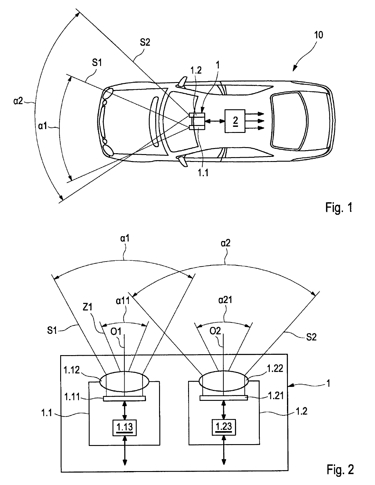
[0044]The vehicle 10 shown in FIG. 1 comprises a driver assistance system with a stereo camera 1 arranged behind a windshield of the vehicle 10 as well as a control and evaluation unit 2, wherein the stereo camera 1 has a first camera 1.1 and a second camera 1.2 and, when viewed in the direction of travel, the first camera 1.1 constitutes a left camera and the second camera 1.2 constitutes a right camera. The image data of the stereo camera 1 are evaluated by the control and evaluation unit 2. A driver assistance function of the driver assistance system is executed as a function of the evaluation result.

[0045]The left camera 1.1 has a camera field of vision S1 with a horizontal opening angle α1, for example of 50°, while the right camera 1.2 has a camera field of vision S2 with a greater horizontal opening angle α2, for example of 90°.

[0046]FIG. 2 shows the design configuration of the stereo camera 1 with the left camera 1.1 and the right camera 1.2. The left camera 1.1 comprises a ...


PUM


Abstract

A stereo camera (1) for a vehicle includes a first camera (1.1), which has a first image sensor (1.11) and the camera field of vision (S1) of which has a first opening angle (α1), and a second camera (1.2), which has a second image sensor (1.21) and the camera field of vision (S2) of which has a second opening angle (α2). The second opening angle (α2) is greater than the first opening angle (α1). The first camera (1.1) has a first lens optical unit (1.12) and the second camera (1.2) has a second lens optical unit (1.22), which both have an angular resolution that is higher in a central region (Z1, Z2) of the field of vision (S1, S2) lying in the angular range (α11, α21) around the optical axis (O1) than outside of the central region. The cameras are arranged so that the fields of vision (S1, S2) overlap.

Description

FIELD OF THE INVENTION[0001]The invention relates to a stereo camera for a vehicle, comprising a first camera, which has a first image sensor, and a second camera, which has a second image sensor. In addition, the invention relates to a method for controlling the exposure of such a stereo camera.BACKGROUND INFORMATION[0002]In order to produce driver assistance systems such as, for example, a traffic sign recognition system or a lane departure warning system, camera systems, in particular stereo cameras, are used for improved depth resolution. The term ‘stereo camera’ denotes two cameras each comprising a lens optical unit and an image sensor, which are mounted offset with respect to one another at a predetermined distance, for example on a windshield of the vehicle. The advantage of stereo cameras is that they can be used to measure distances.[0003]In order to realize the aforementioned driver assistance functions, camera systems require a horizontal opening angle of approx. 50° and...

Claims


Application Information

Patent Timeline
Patent Type & Authority Patents(United States)
IPC IPC(8): B60R11/04H04N13/239H04N5/235H04N13/296G02B13/06H04N13/25B60R11/00
CPCH04N13/296G02B13/06H04N5/2353H04N13/25H04N13/239B60R2011/0026B60R11/04H04N23/73
Inventor ADOMAT, ROLFFECHNER, THOMASKROEKEL, DIETERMUELLER, GERHARDPUNKE, MARTIN
Owner CONTI TEMIC MICROELECTRONIC GMBH
Why Eureka
Try Eureka