Cutting heads for intramedullary reamers

a cutting head and intramedullary technology, applied in the field of cutting heads, can solve the problems of inefficient blade design, unsatisfactory patient outcomes, dull cutting blades, etc., and achieve the effects of reducing manufacturing time, reducing potential disengagement of shafts, and reducing the cost of grinding operations

Active Publication Date: 2019-07-02
VIANT AS&O HLDG LLC
View PDF25 Cites 2 Cited by
  • Summary
  • Abstract
  • Description
  • Claims
  • Application Information

AI Technical Summary

Benefits of technology

[0011]The cutting head comprises a plurality of cutting blades, each having a tissue cutting edge that extends radially from the compound frusto-conical body. The blades are positioned about the cutting head in a spaced apart manner and designed to increase cutting efficiency and debris removal, thereby reducing reactive torque, axial loading, and head pressure during a surgical procedure. The cutting blades are of a unique compound angle construction that improves cutting efficiency. The cutting blades are oriented at an offset angle with respect to a longitudinal axis of the cutting head. In addition, the tissue cutting edge that extends along each blade is oriented at a cutting angle that is different from the blade offset angle. The angled tissue cutting edge is oriented such that it follows an efficient helical curve as it cuts through bone and tissue.
[0012]Moreover, each blade is positioned about the exterior surface of the frusto-conical body at an optimum separation distance between adjacent blades. This optimal separation distance allows for unobstructed removal of intramedullary debris over the cutting head body. The unique blade design of the present invention thus results in increased blade stability, cutting efficiency, and reduced head pressure.
[0015]Furthermore, a protective sleeve may be removably attached to the proximal end of the cutting head barrel portion. The sleeve provides an alternative means in which to secure a drive shaft to the cutting head. In addition, the sleeve provides a protective covering that minimizes potential disengagement of the shaft from the cutting head. In an embodiment, the sleeve comprises a tapered collar that surrounds the drive shaft and attaches to the barrel portion proximal end.
[0016]In an embodiment, the bone cutter of the present invention may be manufactured by a metal injection molding process. In an injection molding process, the bone cutter is fabricated by injecting a composite mixture comprising a powered metal and a binder. The metal injection molding process forms the cutting head and barrel portion having a unitary body construction. Metal injection molding provides a low-cost production process that reduces manufacturing time. In addition, the metal injection molding process avoids the need for expensive grinding operations and assembly of individual blade component pieces.

Problems solved by technology

Using a dull reamer generates heat that typically leads to tissue necrosis and results in undesirable patient outcomes.
A non-sterile reamer blade typically results in an infected and damaged intramedullary space that may lead to other problems for the patient.
However, prior art cutting heads have an inefficient blade design which tends to become increasingly dull, particularly when reaming large portions of bone material within a long bone, such as a femur.
Furthermore, because of their high cost, traditional cutter heads are typically reused multiple times. Over time, as these reamer heads are used and reused, the cutting blades become dull.
As a result, these less efficient prior art cutting heads tend to promote an increase in “head pressure” within the intramedullary canal.
Increasing head pressure within the intramedullary canal may result in the occurrence of a “fat” embolism.
A fat embolism occurs when fat becomes lodged within a blood vessel and obstructs blood flow.
The occurrence of a fat embolism may result in a stroke or even death to the patient.
Unfortunately, there is no simple way to evaluate cutting efficiency after these reamer tools have been used and reused.
In many cases, an ineffective, dull, or contaminated reamer tool is not detected until well into the reaming procedure or even after the procedure is complete.
Poor surgical outcomes such as a damaged intramedullary space can occur as a result of using dull or contaminated reamers.

Method used


Image

  • Cutting heads for intramedullary reamers
  • Cutting heads for intramedullary reamers
  • Cutting heads for intramedullary reamers

Examples


Embodiment Construction

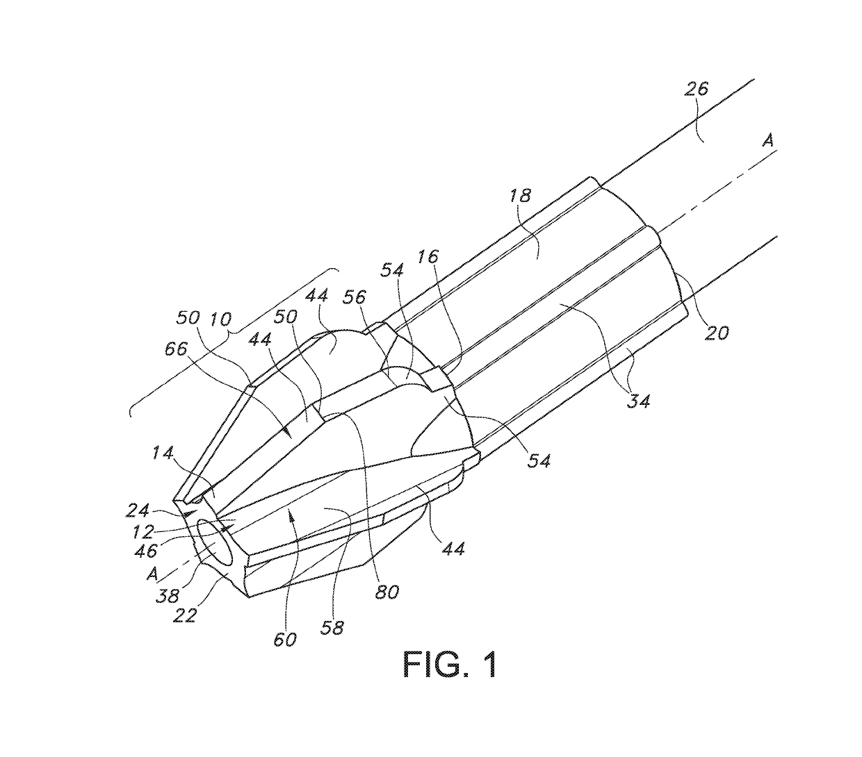
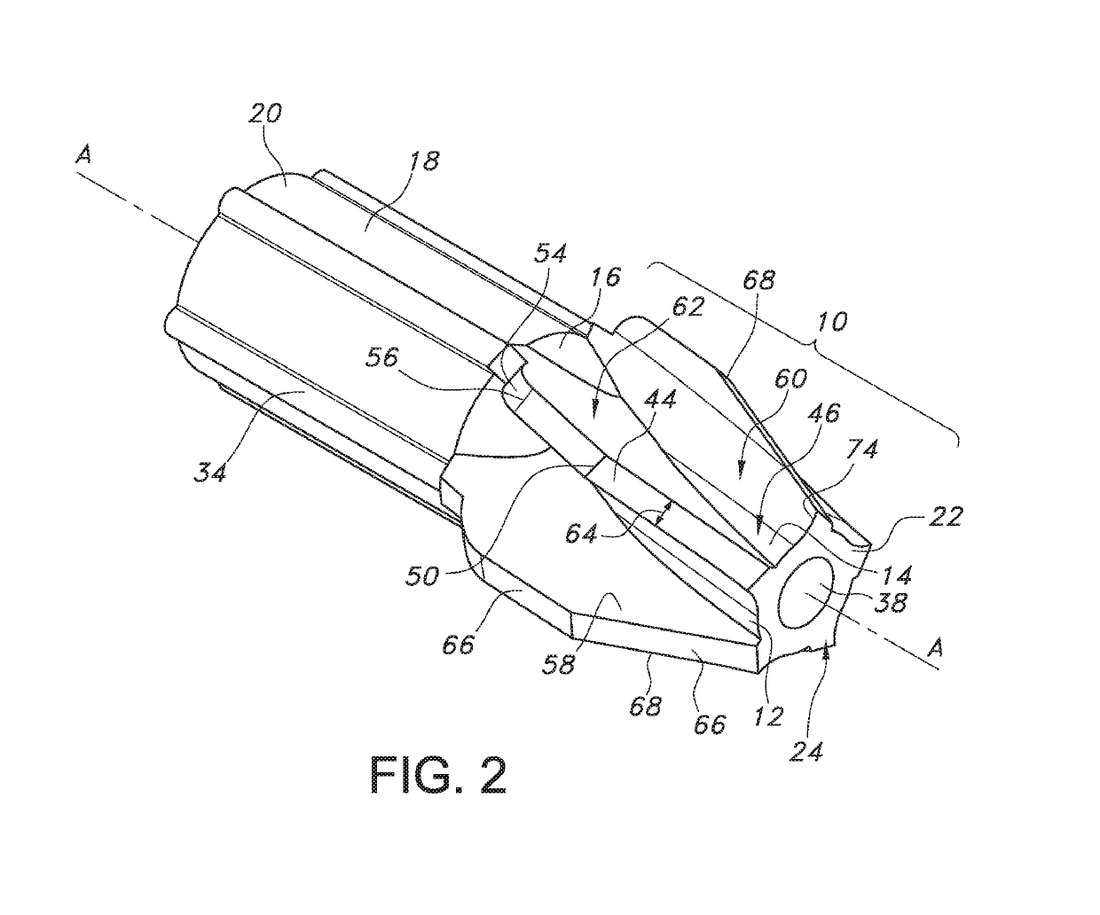
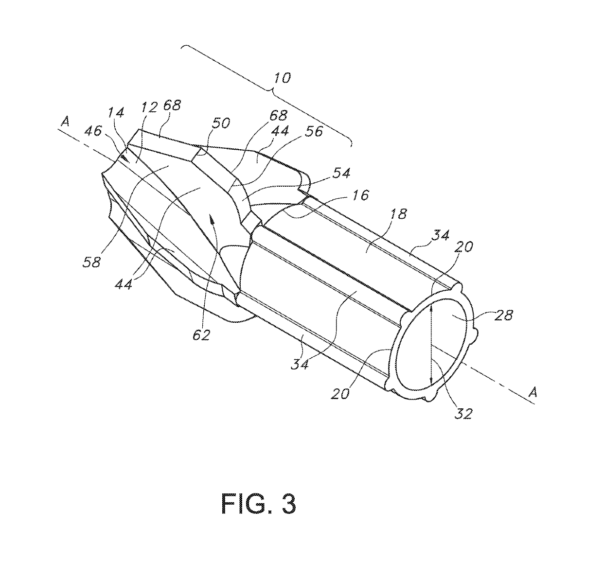
[0030]Now turning to the figures, FIGS. 1-3, 4, 5, and 6 illustrate an embodiment of a bone cutter comprising a cutting head 10 of the present invention. As shown, the cutting head 10 comprises a frusto-conical body 12 that extends lengthwise along a longitudinal axis A-A from a cutting head distal end 14 to a cutting head proximal end 16. In an embodiment, a barrel portion 18 extends in a proximal direction along longitudinal axis A-A from a barrel portion distal end at the cutting head proximal end 16 to a barrel proximal end 20. In an embodiment, the cutting head 10 comprises a distal end wall 22 having an end wall surface 24. In an embodiment, the end wall surface 24 is oriented perpendicular to longitudinal axis A-A. The cutting head 10 provides for the cutting and removal of bone and tissue from a bone during a surgical procedure, for example, during reaming of an intramedullary canal in a femur. The barrel portion 18 provides for the attachment of the cutting head 10 to a dri...


PUM

PropertyMeasurementUnit
relief angleaaaaaaaaaa
rake angleaaaaaaaaaa

Abstract

A bone cutter for use within the intramedullary canal is described. The bone cutter comprises a frusto-conical cutting head that extends to a barrel portion for attachment to a drive shaft. The cutting head comprises a plurality of spaced apart blades having a tissue cutting edge that extends radially from the exterior surface of the cutting head. The plurality of blades are arranged at prescribed angular relationships that are designed to increase cutting efficiency and debris removal, thereby reducing reactive torque, axial loading, and head pressure during a surgical procedure.

Description

CROSS-REFERENCE TO RELATED APPLICATION[0001]This application claims priority from U.S. Provisional Patent Application Ser. No. 62 / 294,642, filed Feb. 12, 2016.FIELD OF THE INVENTION[0002]The present invention relates to the art of orthopedic reamers, and more particularly, to cutting heads used for intramedullary reaming.BACKGROUND[0003]Reamers are tools used in orthopedic procedures to cut bone and associated tissue matter. Specifically, the cutting head of the present invention are designed to cut and bore into the intramedullary space or inner canal of a long bone such as a femur, tibia or humerus. Typically, the intramedullary space of a long bone is reamed to clean and create a space for an implant. As such, these reamers are required to be sterile and sharp. Using a dull reamer generates heat that typically leads to tissue necrosis and results in undesirable patient outcomes. A non-sterile reamer blade typically results in an infected and damaged intramedullary space that may ...

Claims


Application Information

Patent Timeline
Patent Type & Authority Patents(United States)
IPC IPC(8): A61B17/16B22F3/24B22F3/22A61B17/00
CPCA61B17/164A61B17/1615A61B17/1659B22F2003/248A61B2017/00526B22F3/225B22F3/24A61B17/162
Inventor VICTOR, GARY C.SAUSEN, KARI ANNSCHWARTZKOPF, CURTIS J.
Owner VIANT AS&O HLDG LLC
Why Eureka
Try Eureka