
Mounting structure for power unit of utility vehicle

Active Publication Date: 2019-07-02
KAWASAKI MOTORS LTD
View PDF31 Cites 0 Cited by
  • Summary
  • Abstract
  • Description
  • Claims
  • Application Information

AI Technical Summary

Benefits of technology

The present invention is about a mounting structure for a power unit of a utility vehicle that is simplified but can reduce vibration of the power unit. The mounting structure has support portions including front and rear support portions, which help to stabilize the power unit and reduce horizontal vibration. The front support portions are supported by gussets attached to the main frame, which further simplifies the mounting structure. The rear support portion may have more design flexibility and improves stability and performance of a suspension device. The specific configuration of the power unit facilitates transmission of driving power. Overall, the mounting structure of the present invention simplifies the process of mounting the power unit on the vehicle and reduces vibration.

Problems solved by technology

The power unit of the utility vehicle is supported at the number of points, which complicates a mounting structure therefor.

Method used


Image

  • Mounting structure for power unit of utility vehicle
  • Mounting structure for power unit of utility vehicle
  • Mounting structure for power unit of utility vehicle

Examples


Embodiment Construction

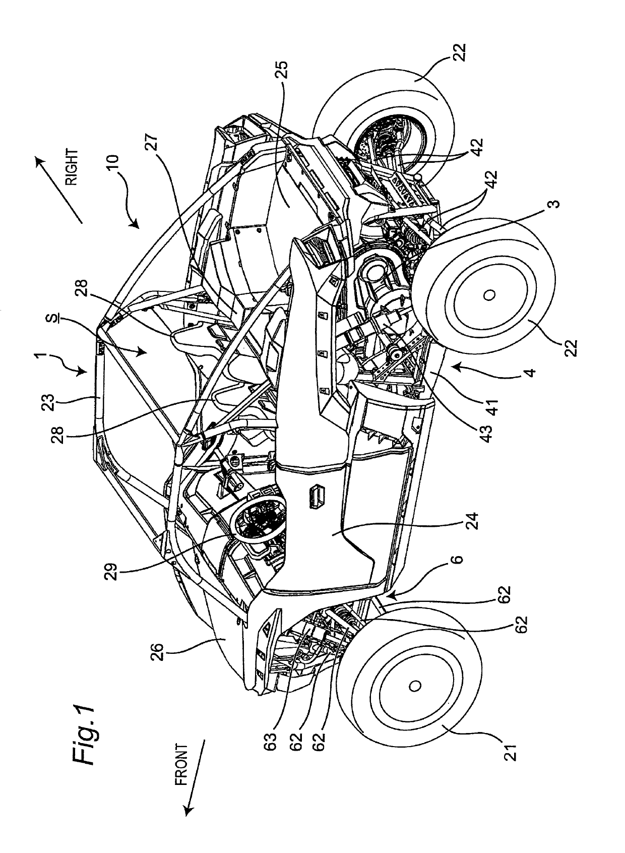
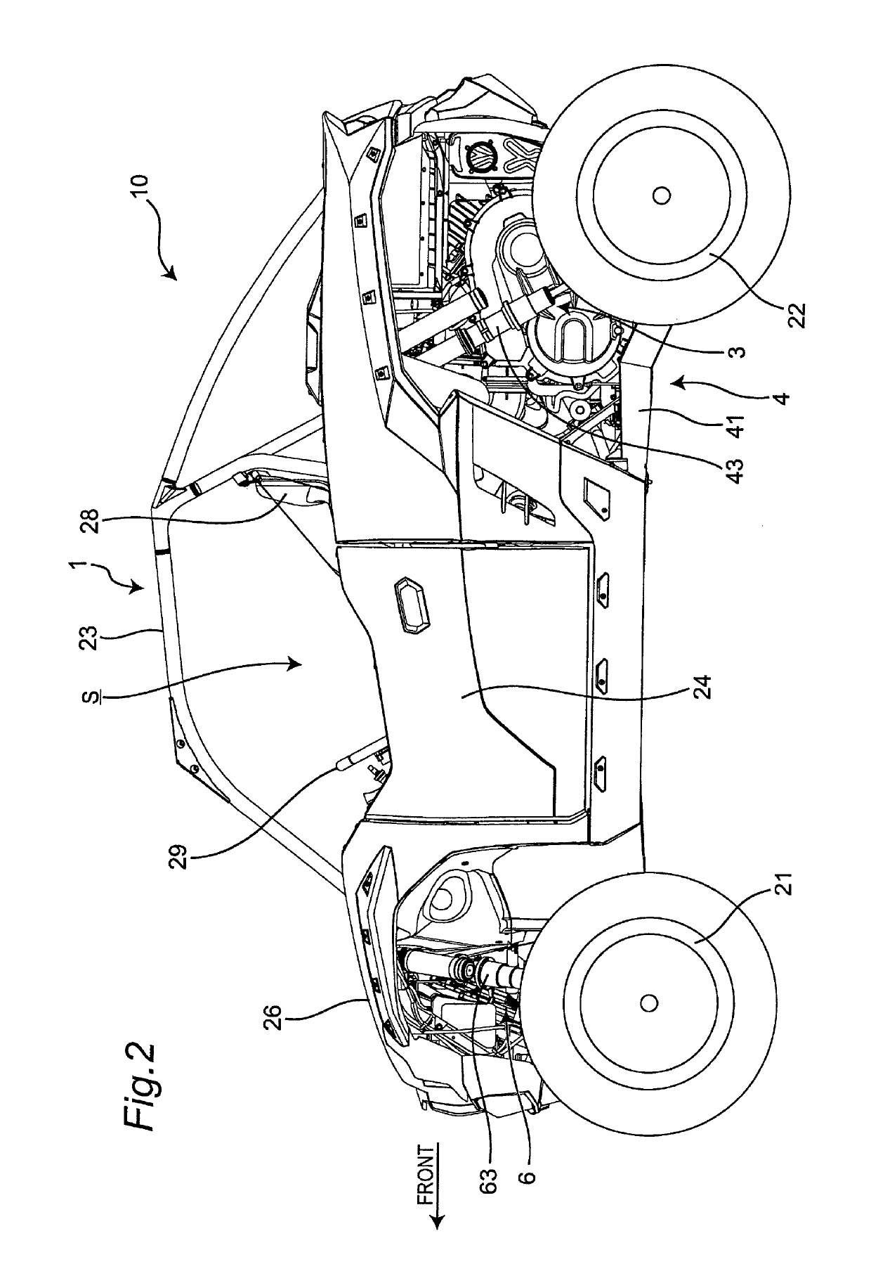
[0028]Hereinafter, a utility vehicle having a mounting structure for a power unit according to an embodiment of the present invention is described with reference to attached drawings. The utility vehicle is a vehicle for off-road traveling which travels not only on a grass field, a gravel field and a sandy field but also on an unpaved mountain road, a forest road, a muddy road, a rocky area or the like. For the sake of convenience of the description, an advancing direction of the utility vehicle is assumed as a “front side” of the utility vehicle and respective parts, and right and left sides in a vehicle width direction when an occupant riding on the utility vehicle faces forward are assumed as “right and left sides” of the utility vehicle and the respective parts.

[0029][Entire Structure of Vehicle]

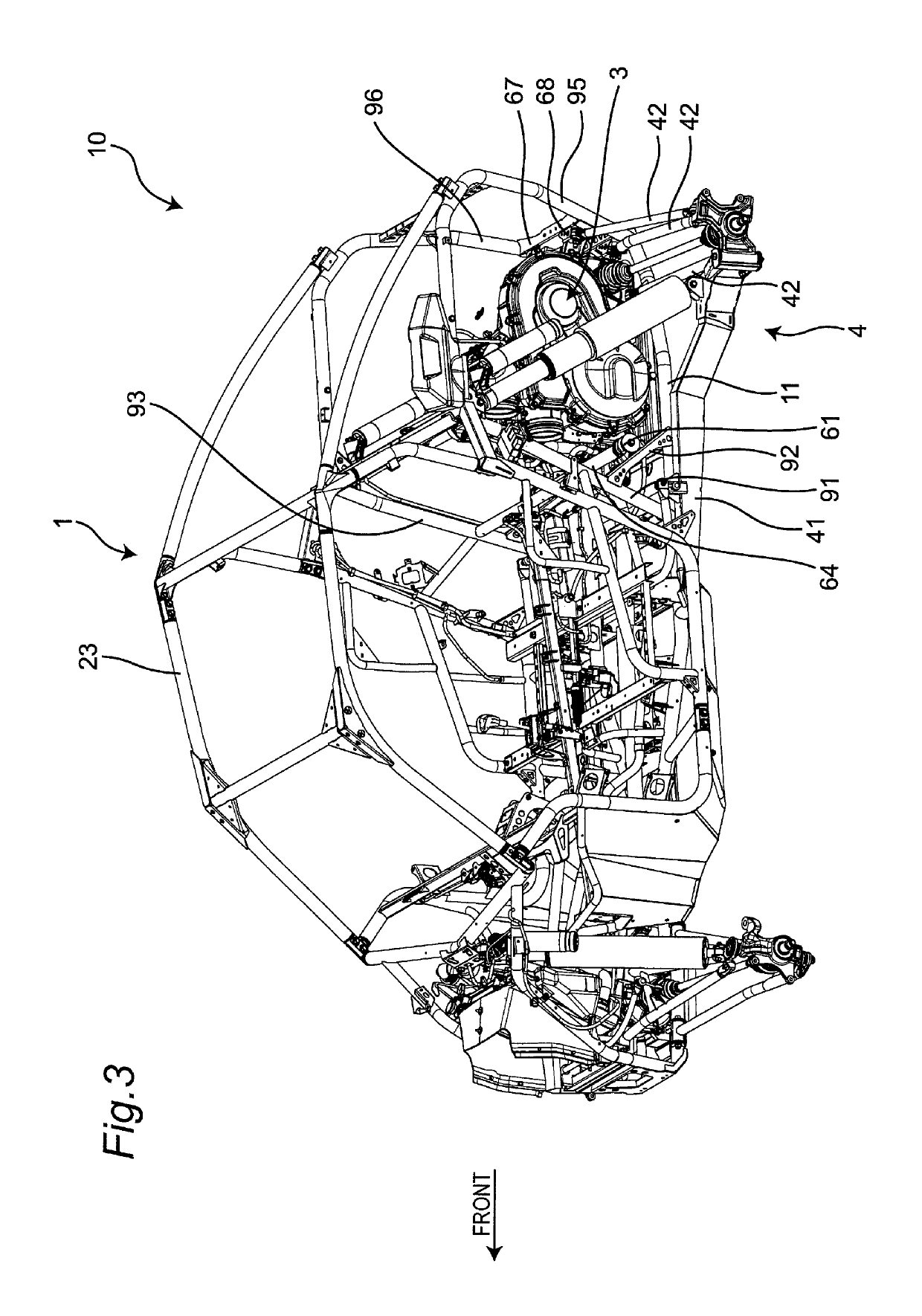
[0030]FIG. 1 is a perspective view of a utility vehicle including a mounting structure for a power unit according to an embodiment of the present invention. FIG. 2 is a left side view of...


PUM


Abstract

The invention provides a mounting structure for a power unit of a utility vehicle. The mounting structure includes a pair of left and right front support portions supporting a front end of the power unit, and a rear support portion supporting a rear end of the power unit. The front support portions and the rear support portion are disposed to cause a centroid of a triangle connecting the front support portions and the rear support portion to agree with a centroid of the power unit in a planar view of the power unit.

Description

BACKGROUND OF THE INVENTION1. Field of the Invention[0001]The present invention relates to a mounting structure for a power unit of a utility vehicle.2. Description of the Related Art[0002]As disclosed in U.S. Pat. No. 9,499,037, a power unit of a utility vehicle is conventionally supported at totally five points including a pair of left and right front portions, a pair of left and right rear portions, and a torque rod.SUMMARY OF THE INVENTION[0003]The power unit of the utility vehicle is supported at the number of points, which complicates a mounting structure therefor.[0004]In view of this, an object of the present invention is to provide a mounting structure for a power unit of a utility vehicle, and the mounting structure is simplified but reduces vibration of the power unit.[0005]In order to achieve the object mentioned above, the present invention provides a mounting structure for a power unit of a utility vehicle, the mounting structure including: a pair of left and right fro...

Claims


Application Information

Patent Timeline
IPC IPC(8): B60K5/02B60K17/08B60K17/24
CPCB60K5/02B60K17/24B60K17/08B60Y2200/124B60K5/00B60K5/1216
Inventor ISHIBASHI, KAZUKIHISADA, KAZUMASAYAMASAKI, AKIYUKIARINO, NAOKI
Owner KAWASAKI MOTORS LTD
Learn More