Control device for internal combustion engine

a control device and internal combustion engine technology, applied in the direction of electric control, machines/engines, output power, etc., can solve the problems of increasing the number of pm in the exhaust and the liable and achieve the effect of suppressing the deterioration of the exhaust emission

Active Publication Date: 2019-07-02
TOYOTA JIDOSHA KK
View PDF15 Cites 5 Cited by
  • Summary
  • Abstract
  • Description
  • Claims
  • Application Information

AI Technical Summary

Benefits of technology

[0007]The present disclosure was made focusing on this problem and has as its object decreasing the number of PM in the exhaust and suppressing deterioration of the exhaust emission in the operating region where the premix can be made to burn by compression ignition.
[0009]According to this aspect of the present disclosure, in the operating region where the premix can be made to burn by compression ignition, it is possible to reduce the number of PM in the exhaust to suppress deterioration of the exhaust emission.

Problems solved by technology

Therefore, in the operating region where the above-mentioned conventional control device of an internal combustion engine makes the premix burn by compression ignition, the number of PM in the exhaust increased and the exhaust emission was liable to deteriorate.

Method used


Image

  • Control device for internal combustion engine
  • Control device for internal combustion engine
  • Control device for internal combustion engine

Examples


first embodiment

[0023

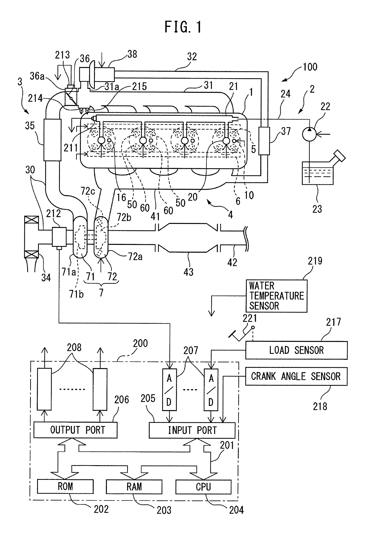
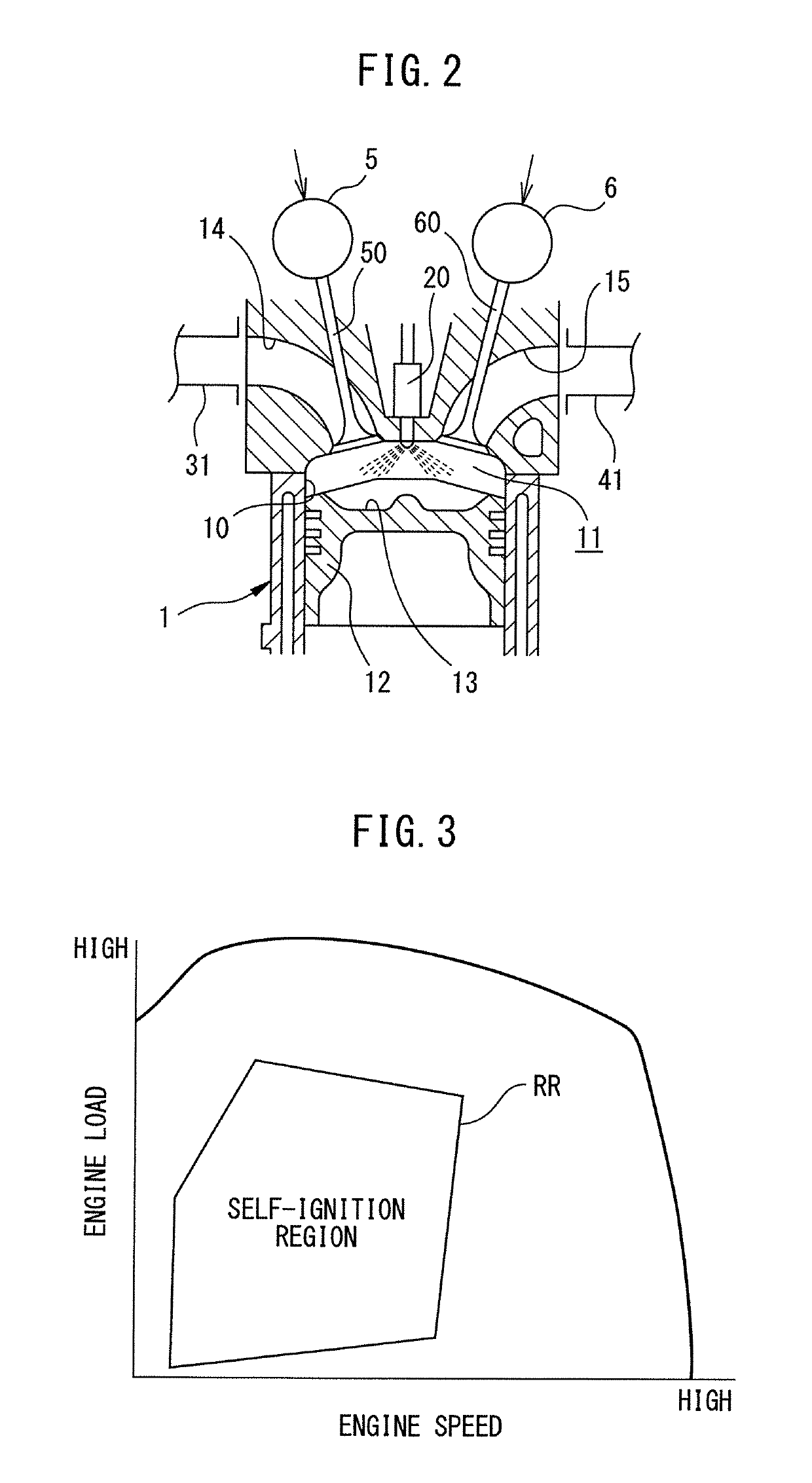
[0024]FIG. 1 is a view of the general configuration of an internal combustion engine 100 and an electronic control unit 200 controlling the internal combustion engine 100 according to a first embodiment of the present disclosure. FIG. 2 is a cross-sectional view of an engine body 1 of the internal combustion engine 100 according to the present embodiment.

[0025]As shown in FIG. 1, the internal combustion engine 100 comprises an engine body 1 provided with a plurality of cylinders 10, a fuel feed system 2, an intake device 3, an exhaust device 4, an intake valve operating device 5, and an exhaust valve operating device 6.

[0026]The engine body 1 burns fuel in combustion chambers 11 formed at the cylinders 10 (see FIG. 2) to for example generate drive force for driving a vehicle etc. The engine body 1 is provided with one spark plug 16 for each cylinder facing the combustion chamber 11 of each cylinder 10. Further, the engine body 1 is provided with a pair of intake valves 50 and a...

second embodiment

[0105

[0106]Next, a second embodiment of the present disclosure will be explained. The present embodiment differs from the first embodiment in the point that when the engine operating state is within the self-ignition region RR and the cooling water temperature TW is less than the second threshold value TW2, fuel is injected from a cylinder fuel injector 20 and a later explained port fuel injector 25. Below, the explanation will center on this point of difference.

[0107]FIG. 10 is a cross-sectional view of an engine body 1 of an internal combustion engine 100 according to the present embodiment.

[0108]As shown in FIG. 10, the fuel feed system 2 of the internal combustion engine 100 according to the present embodiment is further provided with an electronically controlled port fuel injector 25 for injecting fuel into an intake port 14 to indirectly feed fuel to the inside of the combustion chamber 11. The opening time (injection amount) and opening timing (injection timing) of the port f...


PUM


Abstract

A control device for an internal combustion engine is configured to feed fuel to a combustion chamber in an intake stroke to form a homogeneous premix and make the homogeneous premix burn by flame propagation when a temperature of an engine body is less than a first threshold value, to feed fuel to the combustion chamber in the intake stroke to form a homogeneous premix and make the homogeneous premix burn by compression ignition when the temperature of the engine body is the first threshold value to less than a second threshold value larger than the first threshold value, and to directly feed fuel to the combustion chamber in a compression stroke to form a partial premix and make the partial premix burn by compression ignition when the temperature of the engine body is the second threshold value or more.

Description

CROSS-REFERENCE TO RELATED APPLICATION[0001]This application claims priority based on Japanese Patent Application No. 2016-137916 filed with the Japan Patent Office on Jul. 12, 2016, the entire contents of which are incorporated into the present specification by reference.TECHNICAL FIELD[0002]The present disclosure relates to a control device of an internal combustion engine.BACKGROUND ART[0003]JP2014-51927A discloses as a conventional control device of an internal combustion engine a device configured so as to inject fuel into a combustion chamber in a predetermined operating region in a latter half of a compression stroke to make a premix burn by compression ignition and so as to inject fuel in all operating regions in the intake stroke to make the premix burn by flame propagation when the temperature of the engine body is less than a predetermined temperature and it is liable to be unable to stably burn a premix by compression ignition.SUMMARY OF THE DISCLOSURE[0004]However, even...

Claims


Application Information

Patent Timeline
Patent Type & Authority Patents(United States)
IPC IPC(8): F02D41/40F02D35/02F02D41/30F02D13/02F02B11/00F02M26/05F02B1/12F02D41/38F02M26/01
CPCF02D41/40F02D13/0211F02D35/025F02D35/026F02D41/3041F02D41/3076F02D41/3094F02B11/00Y02T10/44F02B1/12F02D13/0238F02D13/0273F02D2041/389F02D2200/021F02M26/01F02M26/05Y02T10/18Y02T10/12Y02T10/40
Inventor KUMAGAE, KOJI
Owner TOYOTA JIDOSHA KK
Why Eureka
Try Eureka