
Start controller for engine

a technology for starting controllers and engines, applied in the direction of engine starters, electric control, combustion engines, etc., can solve the problems of affecting the generation of air-fuel mixtures, affecting the quality of combustion,

Inactive Publication Date: 2019-07-02
TOYOTA JIDOSHA KK
View PDF9 Cites 0 Cited by
  • Summary
  • Abstract
  • Description
  • Claims
  • Application Information

AI Technical Summary

Benefits of technology

This approach allows for immediate recognition of ignition start failures and swift switching to starter motor assistance, preventing the driver's impression of slow engine restarts and ensuring timely engine reactivation.

Problems solved by technology

When the rotational speed of the crankshaft becomes extremely low in the process of the engine stop as described above, an intake air flow in the cylinder also becomes extremely small, which hinders generation of air-fuel mixture from being promoted.
Accordingly, a misfire possibly occurs when an ignition plug attempts to ignite the air-fuel mixture.
Even when the ignition plug ignites the air-fuel mixture, significant combustion pressure cannot be obtained, and the sufficient rotary power cannot be provided to the crankshaft.
As a result, the engine start possibly fails.
More specifically, even in the cases where the restart condition is established in a process of an engine stop and the fuel injection and the ignition are executed in the cylinder in the power stroke to attempt an ignition start as described above, sufficient rotary power cannot be provided to the crankshaft, which results in the failure of the start.
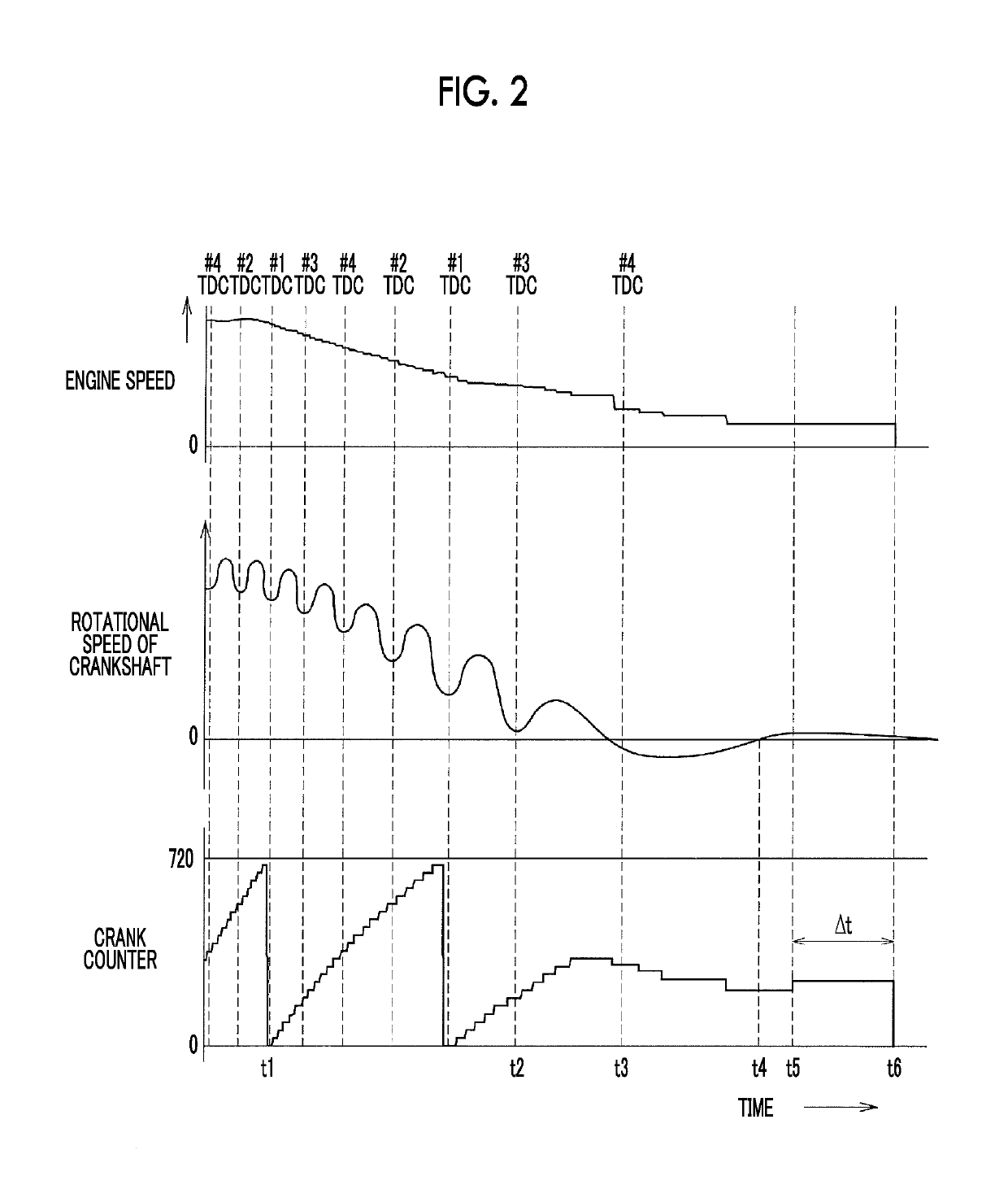
However, because the rotational speed of the crankshaft fluctuates significantly immediately before a stop, it is difficult to set a threshold that is used to determine the failure of the start.
When the threshold is set to be small, an erroneous determination of the failure may be made.
On the other hand, when the threshold is set to be large, the failure of the start may not be recognized.
In addition, even in the case where the failure of the start is determined on the basis of the reverse operation of the crankshaft as described above, the crank signal is not output when the reverse operation is extremely small.
As a result, this reverse operation may not be recognized, that is, the failure of the start may not be recognized.

Method used


Image

  • Start controller for engine
  • Start controller for engine
  • Start controller for engine

Examples


Embodiment Construction

[0025]A description will hereinafter be made on an embodiment of the disclosure with reference to the drawings. As one example of this embodiment, a description will be made on a case where the disclosure is applied to a gasoline engine mounted on a vehicle.

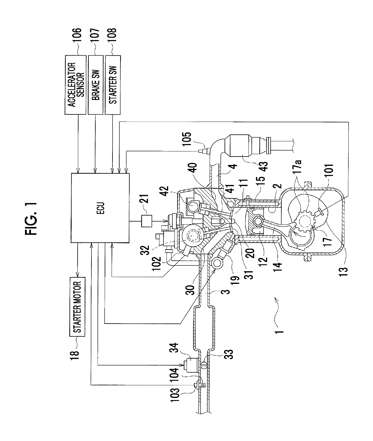
[0026]—Engine Overview—FIG. 1 shows a schematic configuration of an engine 1. The engine 1 of this embodiment is a four-cylinder gasoline engine, and four of first to fourth cylinders 2 (only one is shown in the drawing) each accommodate a piston 12 in a manner to define a combustion chamber 11. The piston 12 and a crankshaft 13 are coupled by a connecting rod 14, and a crank angle sensor 101 that detects a rotation angle (crank angle) of the crankshaft 13 is provided.

[0027]More specifically, a signal rotor 17 is attached to the crankshaft 13, and plural teeth 17a are provided on an outer circumferential surface thereof. The crank angle sensor 101 includes two electromagnetic pickups, for example, and each of the electromagnetic ...


PUM


Abstract

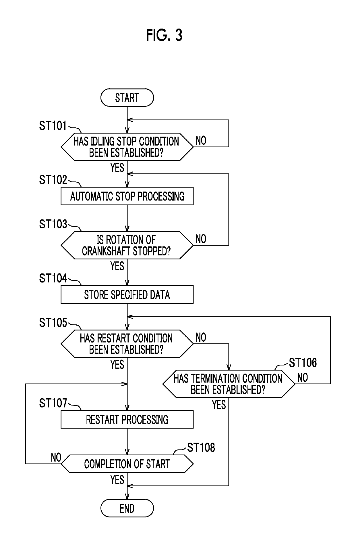
In the cases where a reverse operation of a crankshaft is performed after fuel injection and ignition in a cylinder in a power stroke and it is determined that an engine start is failed, a starter motor is operated, and fuel injection and ignition are executed in the cylinder in the compression stroke to start an engine.

Description

INCORPORATION BY REFERENCE[0001]The disclosure of Japanese Patent Application No. 2016-164917 filed on Aug. 25, 2016 including the specification, drawings and abstract is incorporated herein by reference in its entirety.BACKGROUND[0002]1. Technical Field[0003]The disclosure relates to a controller that restarts an engine without use of a starter motor when a restart condition is established immediately before an engine stop, and, in particular to, a backup technique for a case where a restart is failed.[0004]2. Description of Related Art[0005]Conventionally, a system (an idling stop system) that automatically stops a vehicular engine during idling and automatically restarts the engine thereafter has generally been known. It has been proposed that, when a restart condition is established immediately before a crankshaft stops rotating during an engine automatic stop, such a system restarts the engine (hereinafter also referred to as an ignition start) without use of a starter motor bu...

Claims


Application Information

Patent Timeline
Patent Type & Authority Patents(United States)
IPC IPC(8): F02N11/08F02N99/00
CPCF02N11/0848F02N11/0855F02N99/004F02N11/0814Y02T10/48F02N99/006F02N2250/04F02N2300/2002F02N11/0844F02D41/065F02N19/005F02N2200/022Y02T10/40
Inventor ENOMOTO, HIROSHI
Owner TOYOTA JIDOSHA KK
Learn More