Valve timing control apparatus for internal combustion engine

a timing control and internal combustion engine technology, applied in the direction of machines/engines, non-mechanical valves, couplings, etc., can solve the problem of difficult engine restar

Inactive Publication Date: 2011-11-22
HITACHI LTD
View PDF2 Cites 6 Cited by
  • Summary
  • Abstract
  • Description
  • Claims
  • Application Information

AI Technical Summary

Benefits of technology

[0006]It is an object of the present invention to solve the above-described technical problem in the conventional art and provide a technique capable of holding a rotational phase between a drive rotary member and a driven rotary member in a rotational phase therebetween suitable for the engine start-up by detent torque of an electromagnetic mechanism when the engine is in the stopped state, and thereby serving for performing good restart of the engine.

Problems solved by technology

As a result, it will become difficult to restart the engine.

Method used


Image

  • Valve timing control apparatus for internal combustion engine
  • Valve timing control apparatus for internal combustion engine
  • Valve timing control apparatus for internal combustion engine

Examples


first embodiment

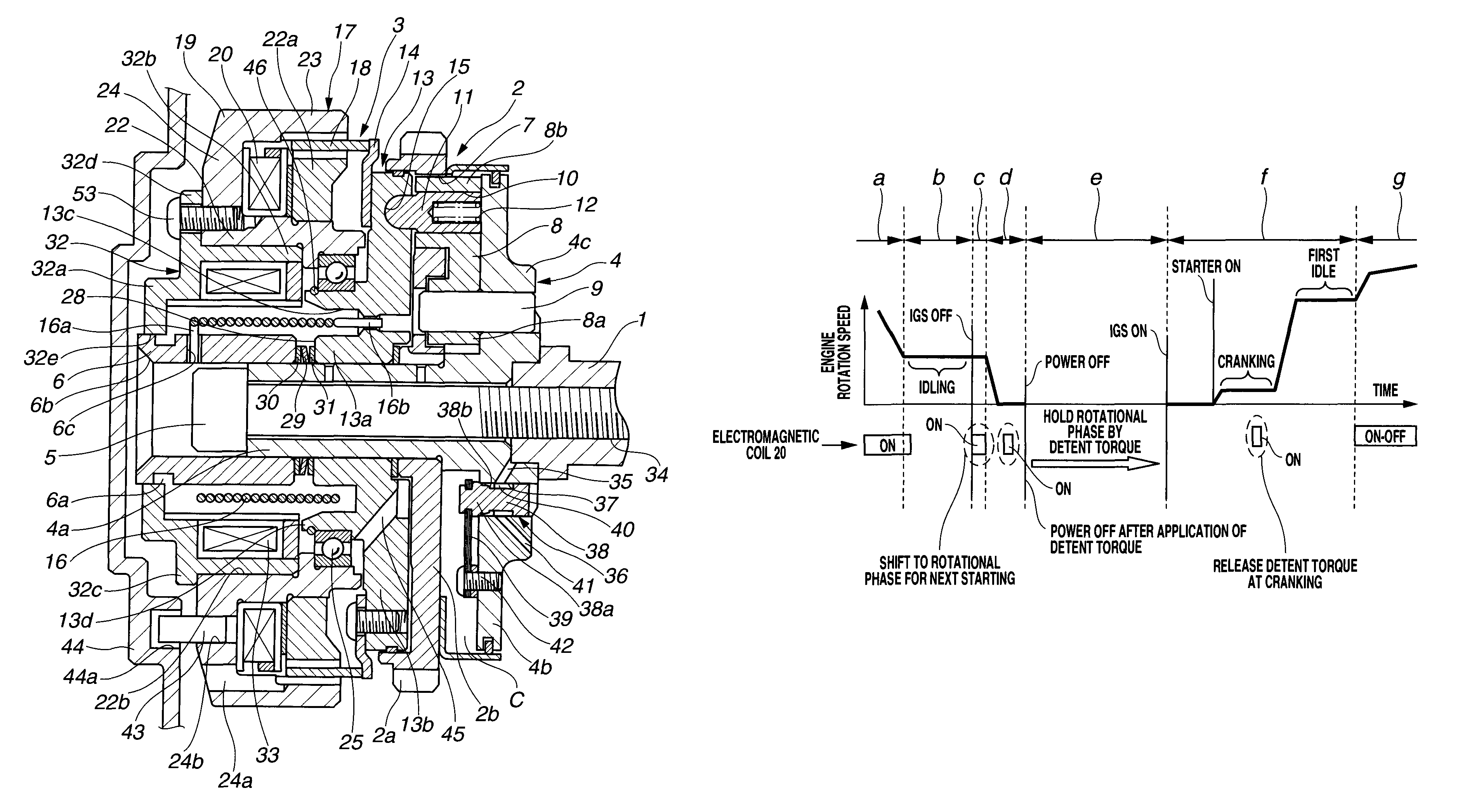
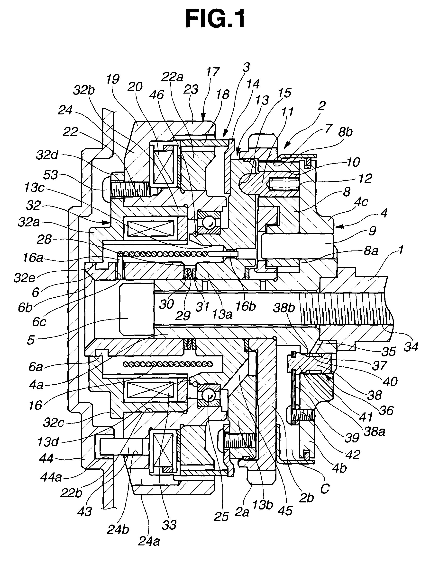
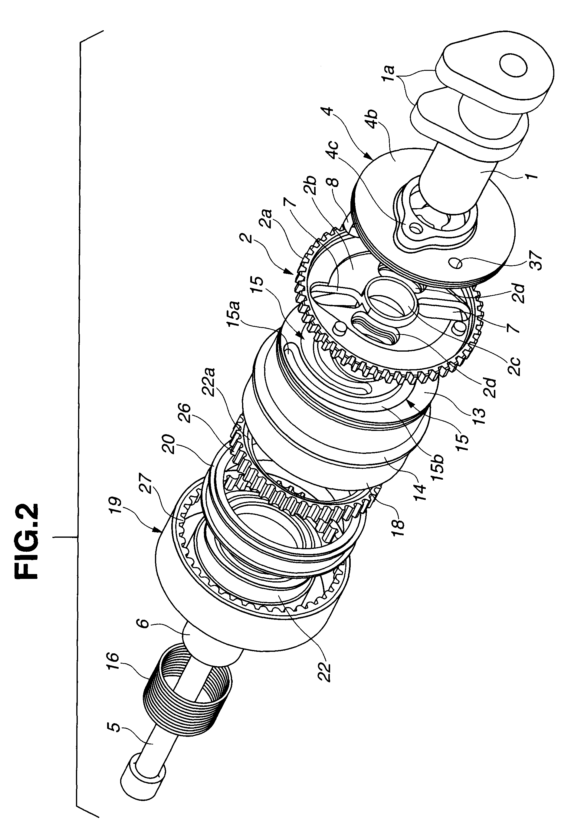
[0035]As shown in FIG. 1 and FIG. 2, the valve timing control apparatus (VTC) includes camshaft 1 that is rotatably supported on a cylinder head, not shown, of the internal combustion engine, timing sprocket 2 that is disposed on a side of a front end of camshaft 1 and rotatable relative to camshaft 1, and rotational phase adjusting mechanism 3 that is disposed on an inner circumferential side of timing sprocket 2 and adjusts the relative rotational phase between camshaft 1 and timing sprocket 2. Rotational phase adjusting mechanism 3 is an electromagnetic mechanism.

[0036]As shown in FIG. 2, camshaft 1 has two cams 1a, 1a on an outer circumferential surface thereof which are provided each cylinder and operative to open intake valves, not shown. As shown in FIG. 1, driven shaft member 4 is connected to a front end portion of camshaft 1 through cam bolt 5 that extends through driven shaft member 4 into the front end portion of camshaft 1 in an axial direction of driven shaft member 4 ...

second embodiment

FIG. 5 shows a second embodiment of the present invention which is the same as the first embodiment except that the electromagnet constituting of the holding canceling mechanism is mounted to VTC cover 44.

[0126]Specifically, first coil yoke 19 and first electromagnetic coil 20 of hysteresis brake 17 are connected with spiral disk 13 through ball bearing 25, and slightly displaceable together with spiral disk 13 in the axial direction.

[0127]Second coil yoke 132 of the electromagnet constituting of the holding canceling mechanism is formed into a generally U-shape in section. Second coil yoke 132 is fitted into annular-shaped support groove 44b that is formed on an inside of an outer circumferential wall of VTC cover 44, and fixed to annular-shaped support groove 44b of VTC cover 44 by means of bolt 47. Second electromagnetic coil 33 is fixedly disposed on an inside of the U-shaped second coil yoke 132. Rear end surface 132a of second coil yoke 132 is opposed to front end surface 24c ...

third embodiment

[0131]FIG. 6 shows a third embodiment of the present invention in which the relative rotational phase holding mechanism is constituted of an electromagnet and the holding canceling mechanism is constituted of a disc spring. In addition, in the third embodiment, the annular groove on the outer circumferential surface of the front end portion of sleeve 6 is omitted.

[0132]Specifically, disc spring 48 constituting the holding canceling mechanism is disposed between front end surface 2e of a cylindrical inner periphery of plate member 2b of timing sprocket 2 and a bottom surface of an annular groove formed on a rear side of an inner circumferential surface of cylindrical inner circumferential portion 13a of spiral disk 13. Disc spring 48 biases spiral disk 13 in a releasing direction in which spiral disk 13 separates from engaging pins 11, namely, in the leftward direction as shown in FIG. 7B. Annular spring retainers 49, 50 are respectively disposed on a front side and a rear side of di...


PUM


Abstract

A valve timing control apparatus for an internal combustion engine, including a drive rotary member that is rotated by the crankshaft, a driven rotary member that transmits rotational force input from the drive rotary member, to the camshaft, and an electromagnetic mechanism that acts to vary a relative rotational phase between the drive rotary member and the driven rotary member. After an ignition switch is turned off and the engine is stopped, the electromagnetic mechanism acts to produce detent torque and hold the relative rotational phase between the drive rotary member and the driven rotary member in a predetermined phase position by the detent torque.

Description

BACKGROUND OF THE INVENTION[0001]The present invention relates to a valve timing control apparatus for an internal combustion engine, which variably controls opening and closing timings of an intake valve and / or an exhaust valve of the engine, for instance, by using a hysteresis brake.[0002]Japanese Patent Application First Publication No. 2004-156508 discloses a valve timing control apparatus for an internal combustion engine including a timing sprocket to which a rotational force is input from an engine crankshaft, a camshaft supported so as to be rotatable with respect to the timing sprocket within a predetermined angular range, a sleeve connected to the camshaft, and a rotational phase adjusting mechanism for adjusting a relative rotational phase between the timing sprocket and the camshaft which is disposed between the timing sprocket and the sleeve.[0003]The rotational phase control mechanism includes a radial guide window formed in the timing sprocket, a spiral guide (a spira...

Claims


Application Information

Patent Timeline
Patent Type & Authority Patents(United States)
IPC IPC(8): F01L1/34
CPCF01L1/352
Inventor WATANABE, MASAHIKO
Owner HITACHI LTD
Why Eureka
Try Eureka