Cable for transmitting electrical signals

a technology of electrical signals and cables, applied in the direction of cables, insulated conductors, conductors, etc., can solve the problems of cable cost and inflexibility, electrical signal crosstalk, and different permittivities of dielectrics

Active Publication Date: 2019-07-09
ROSENBERGER HOCHFREQUENZTECHNIK GMBH & CO KG
View PDF15 Cites 7 Cited by
  • Summary
  • Abstract
  • Description
  • Claims
  • Application Information

AI Technical Summary

Benefits of technology

[0014]According to the invention this problem is solved through a cable of the aforementioned type with the characterizing features of independent claims. Advantageous embodiments of the invention are described in the further dependent claims.

Problems solved by technology

Where several electrical signals are transmitted via different lines of a cable, in addition to increasing the diameter and weight of the cable, the problem also arises that electrical signals crosstalk, in an undesired manner, from one line of the cable into a different line of the cable.
However, this makes the cable expensive as well as inflexible when laying, since the cable as a whole becomes very rigid and certain bending radii may not be exceeded in order not to damage the shielding casing of the lines.
According to US 2010 / 307790 A1 this is problematic because the introduction of different colour pigments into the respective dielectric results in different permittivities for the dielectrics.

Method used


Image

  • Cable for transmitting electrical signals
  • Cable for transmitting electrical signals
  • Cable for transmitting electrical signals

Examples


fourth embodiment

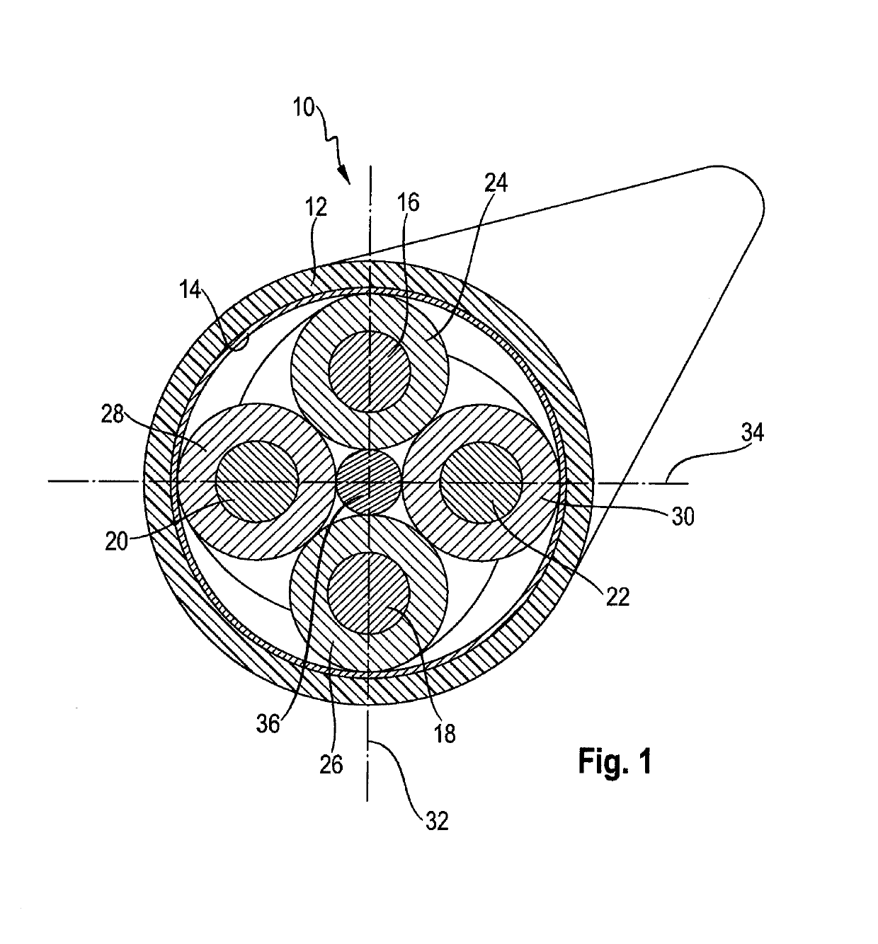
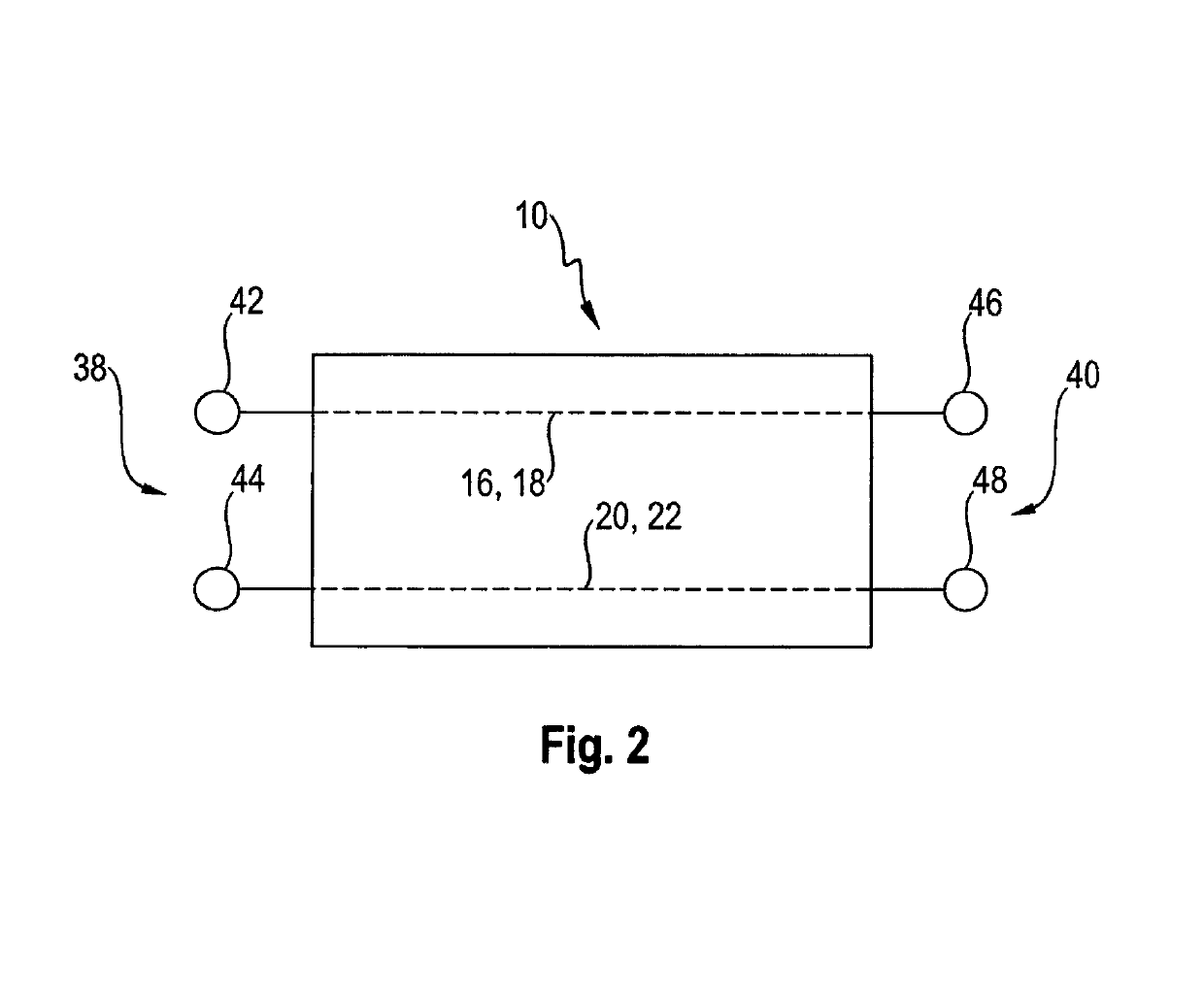
[0071]FIG. 7 shows a fifth preferred embodiment of a cable 10 according to the invention, wherein parts with the same function are identified with the same reference symbols as in FIGS. 1, 4, 5 and 6, so that regarding their explanation reference is made to the above description relating to FIGS. 1, 4, 5 and 6. In FIG. 7, different hatchings or fillings show different values for the relative permittivity εr. An outer casing is not represented in FIG. 7. In this embodiment, the wires 16, 18, 20, 22 are surrounded by identical dielectrics 24, 26, 28, 30, so that their relative permittivity εr is substantially identical. The additional dielectrics 72 and 74 are arranged on the inner side of the shielding casing 14, in each case such that these are each located between a dielectric 24, 26, 28, 30 of the wires 16, 18, 20, 22 and the shielding casing 14. In contrast to the fourth embodiment shown in FIG. 6, the additional dielectrics 72 and 74 are built up in layers with the further diele...

second embodiment

[0072]FIG. 8 shows a sixth preferred embodiment of a cable 10 according to the invention, wherein parts with the same function are identified with the same reference symbols as in FIGS. 1, 4, 5, 6 and 7, so that regarding their explanation reference is made to the above description relating to FIGS. 1, 4, 5, 6 and 7. In FIG. 8, different hatchings or fillings show different values for the relative permittivity εr. An outer casing is not represented in FIG. 8. In this embodiment, the wires 16, 18, 20, 22 are exclusively surrounded by the further dielectric 72 to 74 and the dielectric 72, 74 in each case extends, analogously to the second embodiment according to FIG. 4, from the wires 16, 18, 20, 22 up to the shielding casing 14 and thereby in each case fills a space delimited, in cross section, in parabolic form. In this way, the effective values for the relative permittivity εr(m,n) of the line with the wires 16, 18 differ from the value for the relative permittivity εr(m,n) of the ...


PUM

PropertyMeasurementUnit
relative permittivity εraaaaaaaaaa
relative permittivities εraaaaaaaaaa

Abstract

A cable for transmitting electrical signals including an outer casing made of an electrically insulating material and at least N lines n with N≥2 and N€N which are arranged within the outer casing, wherein each line m has a total of M wires made of an electrically conductive material with M≥1 and M€N, wherein the wire m with m€[1, M], m€N, the line n with n E [1, N], n€N is surrounded by a dielectric having a predetermined value for the relative permittivity er(m,n)>1, wherein for each line n the value for the relative permittivity of the dielectrics (24. 26. 28. 30) of the wires (16, 18, 20, 22) of this line n is identical, except for deviations resulting from the manufacturing process, so that er(p·n)=er(p+q,n), where q€[1, M−p], q€Np € [1, M−1], p€N.

Description

BACKGROUND OF THE INVENTION1. Field of the Invention[0001]The invention relates to a cable for transmitting electrical signals comprising an outer casing made of an electrically insulating material and at least N lines n with N≥2 and N∈ which are arranged within the outer casing, wherein each line m has a total of M wires made of an electrically conductive material with M≥1 and M∈, wherein the wire m with m∈[1, M], m∈, the line n with n∈[1, N], n∈ is surrounded by a dielectric having a predetermined value for the relative permittivity εr(m,n)>1 wherein for each line n the value for the relative permittivity of the dielectrics (24, 26, 28, 30) of the wires (16, 18, 20, 22) of this line n is identical, except for deviations resulting from the manufacturing process, so that εr(p,n)=εr(p+q,n), where q∈[1, M−p], q∈, p∈[1, M−1], p∈.2. Description of Related Art[0002]A cable for transmitting electrical signals contains wires made of a conductive material, which for the purpose of mutual...

Claims


Application Information

Patent Timeline
Patent Type & Authority Patents(United States)
IPC IPC(8): H01B11/00H01B7/02H01B11/08H01B3/30
CPCH01B11/005H01B7/0216H01B11/08H01B7/02H01B3/30H01B11/06
Inventor ARMBRECHT, GUNNARSCHMID, THOMASKUNZ, STEPHAN
Owner ROSENBERGER HOCHFREQUENZTECHNIK GMBH & CO KG
Why Eureka
Try Eureka