Electric power converting apparatus with inner plane of control board fixed to housing
a technology of electric power converting apparatus and control board, which is applied in the direction of electric apparatus casing/cabinet/drawer, dc-ac conversion without reversal, transportation and packaging, etc., can solve problems such as damage to mounted parts, and achieve high-density mounting, increase vibration resistance, and reduce size
- Summary
- Abstract
- Description
- Claims
- Application Information
AI Technical Summary
Benefits of technology
Problems solved by technology
Method used
Image
Examples
embodiment 1
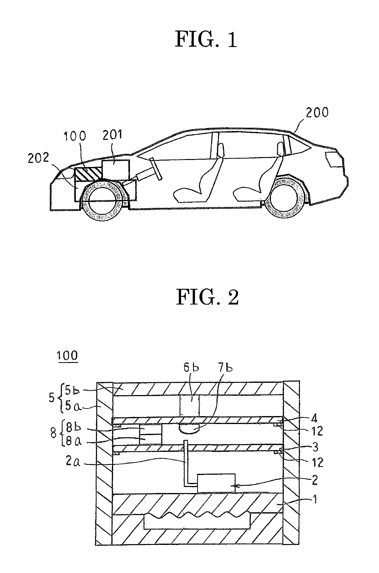
[0025]FIG. 1 is a schematic diagram that shows an automobile to which is mounted an electric power converting apparatus according to Embodiment 1 of the present invention, FIG. 2 is a cross section that schematically shows a construction of the electric power converting apparatus according to Embodiment 1 of the present invention, and FIG. 3 is a transparent oblique projection that schematically shows the construction of the electric power converting apparatus according to Embodiment 1 of the present invention.
[0026]As shown in FIG. 1, an electric power converting apparatus 100 is mounted above a transaxle 202 inside an engine compartment on which vibrational loads from an engine 201 of an automobile 200 and from a road surface easily act, for example.
[0027]Next, configuration of the electric power converting apparatus 100 will be explained with reference to FIGS. 2 and 3.
[0028]The electric power converting apparatus 100 includes: a power module 2 that incorporates a plurality of po...
embodiment 2
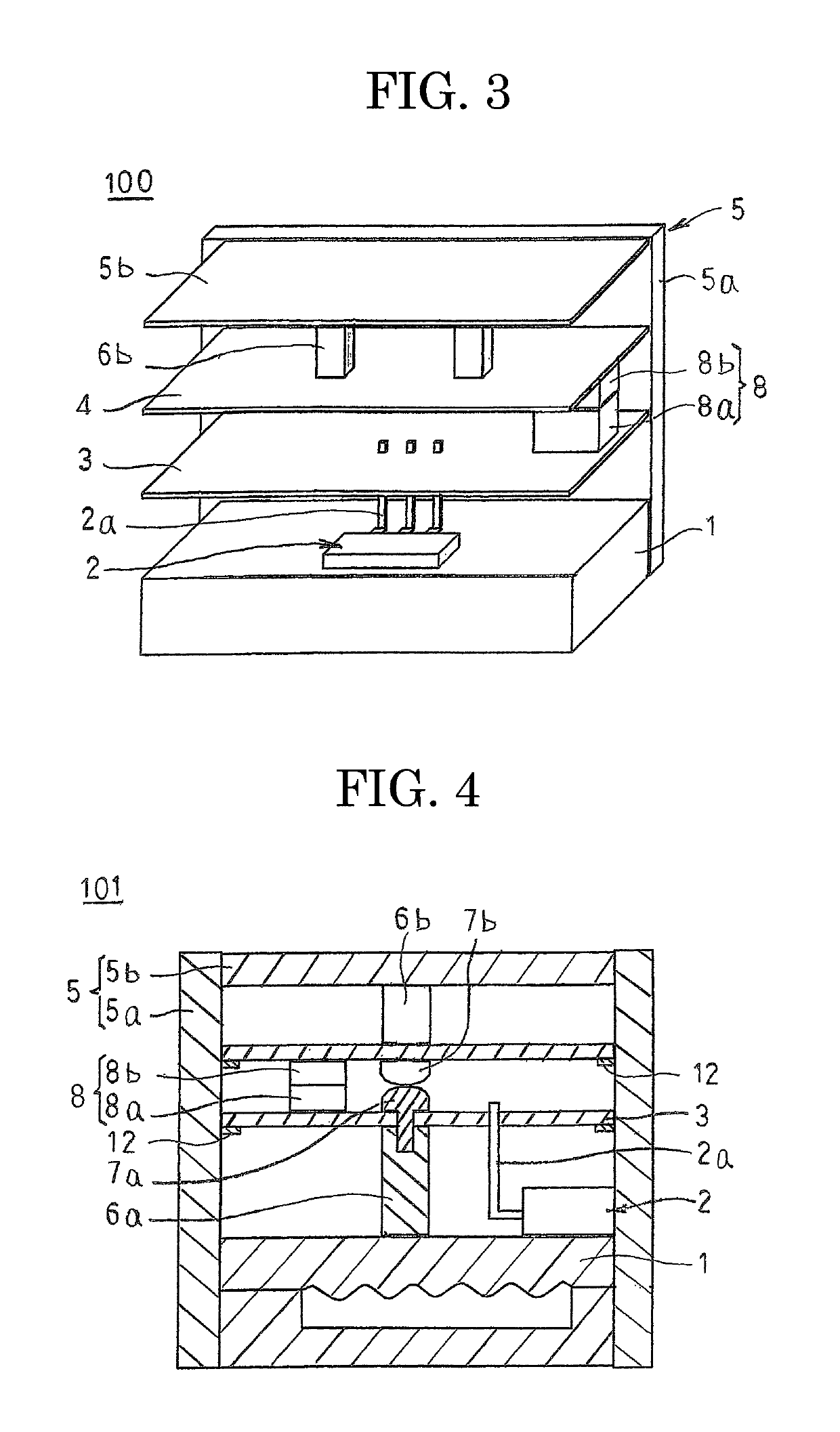
[0050]FIG. 4 is a cross section that schematically shows a construction of an electric power converting apparatus according to Embodiment 2 of the present invention, and FIG. 5 is a transparent oblique projection that schematically shows the construction of the electric power converting apparatus according to Embodiment 2 of the present invention.
[0051]In FIGS. 4 and 5, first supporting posts 6a are fixed to an upper surface of a cooler 1 using a solder, a sintered material of silver nanoparticles, a liquid phase diffusion binder such as copper-tin, silver-tin, etc., an adhesive, or screws, etc. A first controlling circuit board 3 is fixed to the cooler 1 by means of the first supporting posts 6a by being fixed by screws 7b to the first supporting posts 6a, The first supporting posts 6a constitute a first fixing member.
[0052]Moreover, a remainder of the configuration is configured in a similar or identical manner to that of Embodiment 1 above.
[0053]In an electric power converting ap...
embodiment 3
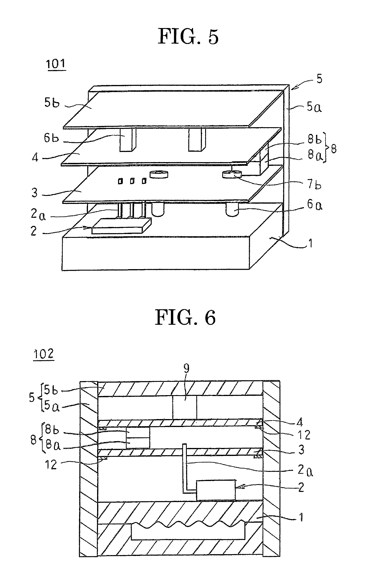
[0059]FIG. 6 is a cross section that schematically shows a construction of an electric power converting apparatus according to Embodiment 3 of the present invention, and FIG. 7 is a transparent oblique projection that schematically shows the construction of the electric power converting apparatus according to Embodiment 3 of the present invention.
[0060]In FIGS. 6 and 7, surface mounted components 9 that are mounted to an inner plane of a second controlling circuit board 4 are fixed to a lower surface of the cover portion 5b by adhesive. The surface mounted components 9 constitute a second fixing member.
[0061]Moreover, a remainder of the configuration is configured in a similar or identical manner to that of Embodiment 1 above.
[0062]In an electric power converting apparatus 102 according to Embodiment 3, the first controlling circuit board 3 is fixed to the cooler 1 by means of the signal terminals 2a of the power module 2, and the second controlling circuit board 4 is fixed to the c...
PUM
 Abstract
Description
Claims
Application Information
 - R&D
- Intellectual Property
- Life Sciences
- Materials
- Tech Scout
- Unparalleled Data Quality
- Higher Quality Content
- 60% Fewer Hallucinations
Browse by: Latest US Patents, China's latest patents, Technical Efficacy Thesaurus, Application Domain, Technology Topic, Popular Technical Reports.
© 2025 PatSnap. All rights reserved.Legal|Privacy policy|Modern Slavery Act Transparency Statement|Sitemap|About US| Contact US: help@patsnap.com


