
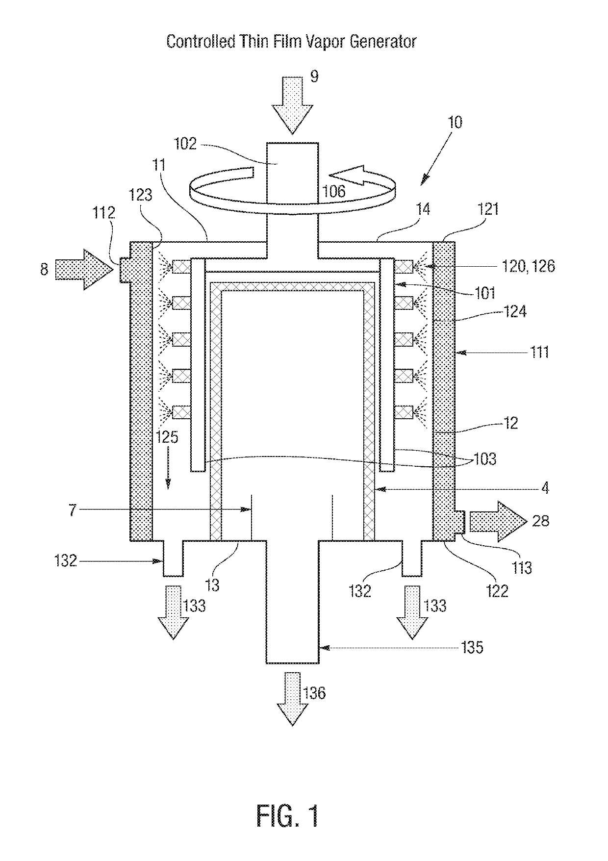
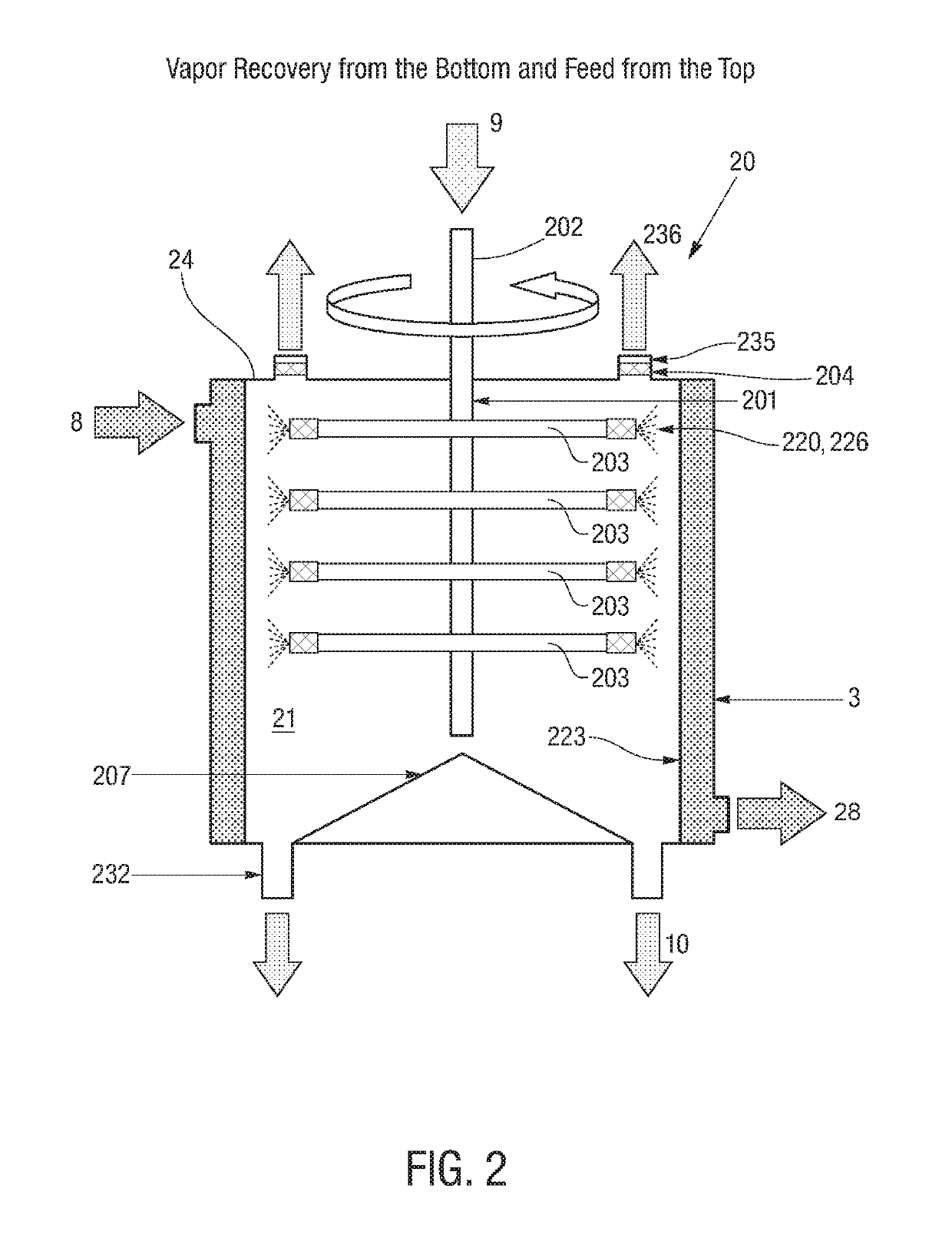
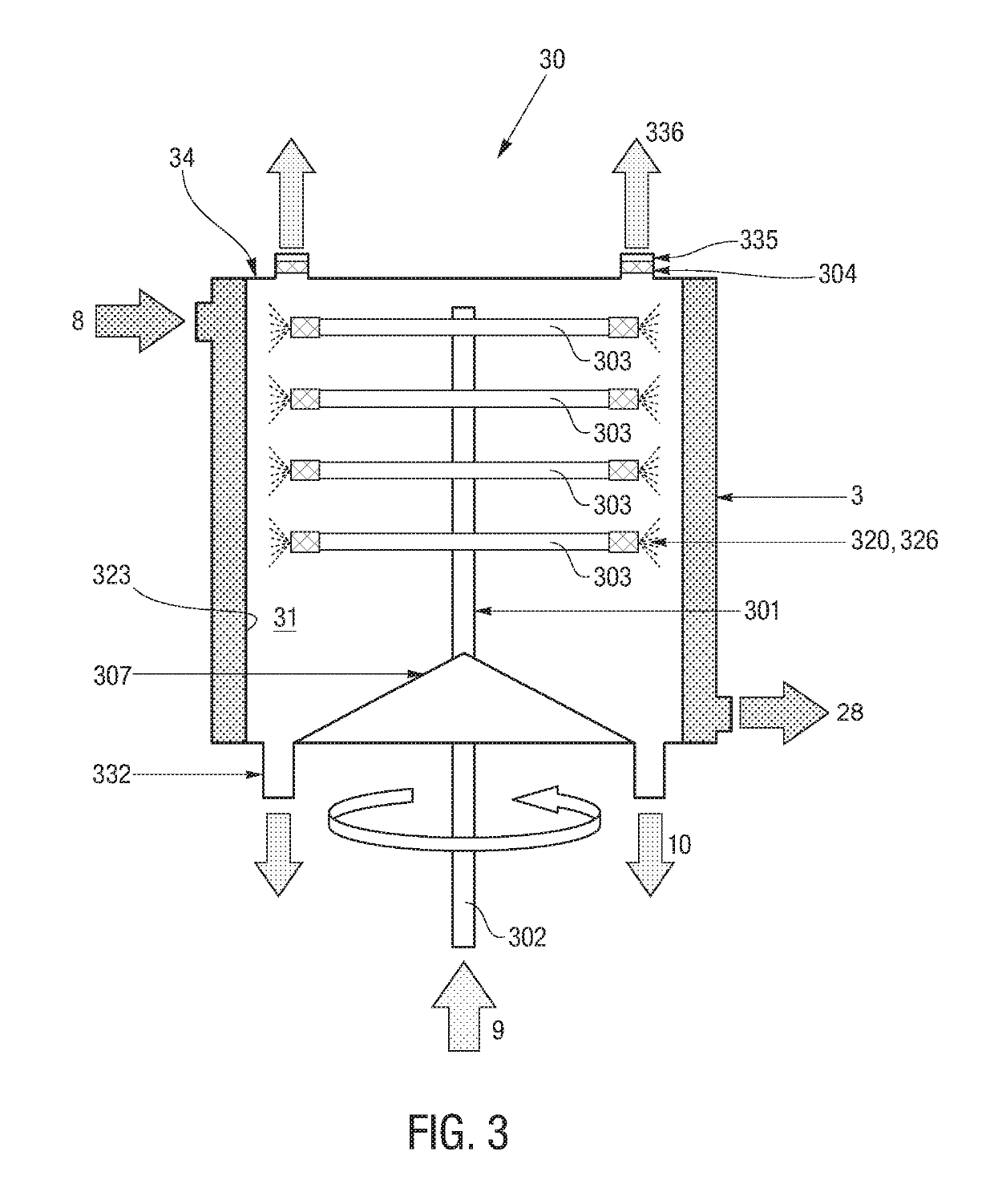
Controlled thin film vapor generator for liquid volume reduction

a thin film vapor generator and liquid volume technology, which is applied in the direction of multiple-effect evaporation, waste water treatment from quaries, separation processes, etc., can solve the problems of corrosion, heat transfer surface scaling, unwanted drying and scaling about the heat transfer surface, etc., to facilitate the processing of fluids and increase the surface area for processing

Inactive Publication Date: 2019-07-16
R3 FUSION
View PDF3 Cites 3 Cited by
  • Summary
  • Abstract
  • Description
  • Claims
  • Application Information

AI Technical Summary

Benefits of technology

[0004]The present disclosure is directed to a reactor for processing a fluid. The reactor, in various embodiments, may include a plurality of vessels, each having at least one heat exchange surface along which the fluid being processed can flow as a thin film. The plurality of vessels may be arranged in a substantially concentric manner so as to provide increased surface area for processing within a given footprint. Annular spaces between adjacent vessels may accommodate the fluid being processed and by-products thereof. The reactor further includes a pathway for directing a heat exchange fluid, such as steam, from one vessel to an adjacent vessel. The heat exchange fluid serves to create a temperature differential between the heat exchange surfaces of the vessels and the fluid being processed therealong to facilitate processing of the fluid.
[0005]The pathway, in various embodiments, may extend continuously amongst the plurality of vessels. In one such embodiment, the pathway may extend about a circumference of each successive vessel before continuing to an adjacent vessel. The pathway may be defined in part by a gap between an inner surface and an outer surface of each vessel extending about the circumference of the vessel. The pathway may be further defined by one or more conduits connecting the gaps of each successive vessel to provide for the heat exchange fluid to flow continuously between the vessels. These conduits, in an embodiment, may be situated on alternating sides of the reactor such that the pathway enters the gap of a given vessel and travels substantially about the circumference of that vessel before travelling into the gap of the next vessel via the conduit(s) therebetween. Conduits may be distributed axially along each of the gaps to provide for substantially uniform axial distribution of the heat exchange fluid throughout each of the gaps.
[0007]In some embodiments, the vapor outlet may be configured to direct the generated vapor into the atmosphere or into a reservoir, and the processed fluid outlet may be configured to direct the processed fluid towards a reservoir for collection. The system, in such a configuration, may be useful for reducing the volume of the fluid needing to be stored, transported, or the like.
[0008]In other embodiments, the system may further include a vapor pathway, in fluid communication with the vapor outlet, for directing the vapor exiting the reactor towards a heat exchange fluid inlet of the reactor. The generated vapor directed along this pathway may contribute to heat transfer with the fluid being processed in the reactor. A compressor may be provided along the pathway for compressing the vapor and thereby adding thermal energy to the vapor. Condensation, resulting from heat transfer away from the vapor, may be directed along a condensate pathway for collection. The processed fluid exiting the reactor through the processed fluid outlet may be directed along a processed fluid pathway towards a reservoir for collection. The system, in such a configuration, may be useful for reducing the volume of the fluid needing to be stored, transported, or the like, as well as for recovering a portion of the fluid as fresh water.

Problems solved by technology

A common problem in chemical reaction processes is how to achieve the proper hydrodynamics in the reactor to efficiently produce the desired products.
In evaporators, for example, non-uniform evaporation of a fluid against the heat transfer surface causes unwanted drying and scaling about the heat transfer surface.
In extreme cases, the reduction in the film thickness creates a dry spot, which eventually results in scaling of the heat transfer surface evaporate surface and corrosion.

Method used


Image

  • Controlled thin film vapor generator for liquid volume reduction
  • Controlled thin film vapor generator for liquid volume reduction
  • Controlled thin film vapor generator for liquid volume reduction

Examples


example i

[0117]An example is provided to further understanding to the present invention. In this example, reactor 70 is approximately 26.25 inches in diameter, giving it a footprint of approximately 3.8 square feet. Processed fluid enters through a 1 to 2 inch diameter fluid inlet 702 and exits through a 3 inch diameter reject outlet 734. Evaporation from the fluid being processed exits through three evaporation outlets 742, each about 4 inches in diameter. Steam enters through three steam inlets 75, each about 4 inches in diameter, and condensate formed from the steam during processing exits through a 3 inch diameter outlet 755.

[0118]Reactor 70 includes four concentrically arranged vessels 71a-d, each about 66 inches in height except for the outermost vessel, which is 72 inches in height. Outermost vessel 71a includes an inner heat exchange surface 723a, and vessels 71b-d internal thereto each include inner and outer heat exchange surfaces 723b-d, 724b-d, respectively, for a total of seven ...


PUM

PropertyMeasurementUnit
widthaaaaaaaaaa
widthaaaaaaaaaa
thicknessaaaaaaaaaa

Abstract

A reactor comprising a plurality of vessels, each having a heat exchange surface for processing a fluid as a thin film flow, the vessels arranged in a concentric manner; a plurality of annular spaces situated between the vessels; and a pathway for directing a heat exchange fluid from one vessel to an adjacent vessel for creating a temperature differential between the heat exchange surfaces and the fluid being processed. A system comprising a fluid source, a reactor, and a vapor outlet and a processed fluid outlet through generated vapor and processed fluid are directed out of the reactor, respectively. A method comprising providing a plurality of concentrically arranged surfaces in spaced relation, distributing a fluid to be processed against the surfaces in a controlled manner to form a substantially uniform thin film flow thereon, and evaporating at least a portion of the fluid being processed along the plurality of surfaces.

Description

TECHNICAL FIELD[0001]The present invention relates to processing reactors, and more particularly, to continuous processing reactors that can impart fluid being processed with high heat transfer and high transport rates. The present invention relates, in particular, to the use of thin film heat transfer for producing vapors, which can be vented, condensed or compressed and can act as a continuous source for the generation of vapor, and for continuous evaporation or distillation of fluids.BACKGROUND[0002]A common problem in chemical reaction processes is how to achieve the proper hydrodynamics in the reactor to efficiently produce the desired products. In evaporators, for example, non-uniform evaporation of a fluid against the heat transfer surface causes unwanted drying and scaling about the heat transfer surface. For example, as evaporation takes place in conventional thin film reactors, the film thickness of the liquid film undergoing evaporation is continuously reduced. In extreme...

Claims


Application Information

Patent Timeline
Patent Type & Authority Patents(United States)
IPC IPC(8): B01D1/22B01B1/00B01D1/28B01D1/26B01D1/16B01J4/00B01J19/18B01J19/00C02F1/08C02F103/06C02F103/08C02F103/10
CPCB01D1/22B01D1/16B01D1/223B01D1/26B01D1/28B01D1/2856B01J4/002B01J4/007B01J19/006B01J19/0066B01J19/1843B01J19/1887C02F1/08B01B1/005Y02A20/128B01J2219/00081B01J2219/00085B01J2219/00094B01J2219/00774C02F2103/06C02F2103/08C02F2103/10Y02A20/124
Inventor CAMPBELL, ROBERTSCHALM, JEANE A.
Owner R3 FUSION
Learn More